
Long-stroke deep-well pumping unit

a technology of pumping unit and sucker rod, which is applied in the direction of piston pumps, borehole/well accessories, fluid couplings, etc., can solve the problems of sucker rod lifting system, rod string deformation or breakage, and large amount of rod string

Inactive Publication Date: 2006-02-02
SMITH NORRIS EDWARD
View PDF21 Cites 40 Cited by
  • Summary
  • Abstract
  • Description
  • Claims
  • Application Information

AI Technical Summary

Problems solved by technology

To access hydrocarbon fluid within a well, it is often necessary to drill a wellbore to a high depth within the formation, often termed a “deep well.” Pumping fluid from deep wells using a sucker rod lifting system is problematic for several reasons.
First, the downhole positive displacement pump is submerged in the downhole fluid so that the positive displacement pump may fill with the surrounding production fluid upon reciprocation of the rod string, and because the fluid level of a deep well is typically located at a high depth within the wellbore, the rod string which connects the positive displacement pump to the drive mechanism must be long to access the fluids.
Therefore, the high length of the rod string as well as the material which makes up the rod string causes the rod string to weigh a large amount.
The length of the motion of the rod string and the weight of the rod string cause the rod string to possess a high momentum at the end of the up-stroke and down-stroke, often causing the rod string to deform or break when motion is stopped between the up-stroke and down-stroke (at the “turnaround”).
Specifically, the elastic nature of the material of which the rod string is constructed makes the rod string vulnerable to rod stretch, especially at the turnaround between the down-stroke and the up-stroke where the momentum of the rod string is most difficult to stop.
Moreover, the stresses imposed on the rod string by a mismatch between the dynamic characteristics of the surface drive unit and the rod string may cause the rod string to break.
Generally, rod string motion problems include premature rod string separation due to material fatigue, damage to the well tubing in which the rod string reciprocates and instantaneous rod string loads beyond the design limit due to suddenly applied loads from dynamic mismatch.
The downhole pump efficiency is affected by unfavorable rod string motion in other ways.
Rod string motion problems, including rod string damage, tubing damage, and only partial filling of the pump, increase as the load on and speed of the rod string are increased.
Sucker rod lifting systems include the additional problem when the well is pumped down to the point where fluid only partially fills the downhole pump barrel during the up-stroke of the rod string.
Another problem with deep-well sucker rod lifting systems is that the difference between the loading on the rod string during the up-stroke and the loading on the rod string during the down-stroke is severe.
This uneven loading requires a massive amount of horsepower for the drive mechanism to lift the rod string on the up-stroke, while limited horsepower is necessary for the rod string to fall into the wellbore on the down-stroke.
Uneven loading in deep well pumps constitutes an inefficient use of horsepower because of the high amount of work expended in moving the rod string upward which is then not recovered upon the rod falling downward.
Similarly erratic, on the down-stroke, the loading drastically decreases to point R from point K, then increases to point S, then decreases again before increasing back to point J. This erratic loading on the rod string often stretches, breaks, or otherwise damages the rod string.
Additionally, this erratic loading does not make efficient use of the horsepower which drives the drive mechanism.
While the inter-cyclic speed is good for this drive mechanism, as is evidenced by the favorable rod string motion profile shown in FIG. 5B, the loading on the rod string at the turnarounds of the rod string is not desirable.
The jarring of the rod string also causes damage to the rod string, which may include breaking or stretching of the rod string.
The amount of time the rod string spends at the top and the bottom of the stroke is not long enough to produce a good, smooth turnaround.
In gear-driven mechanical drive mechanisms, an electric motor rotates a gear reducer, and the gear reducer restricts the load and speed capacity of the mechanical drive mechanism.
A problem with the mechanically-driven pumping units is that gear-driven pumping units are not very responsive to speed changes of the polished rod.
Gear-driven pumping units possess inertia from previous motion so that it is difficult to stop the units or change the direction of rotation of the units quickly.
Therefore, jarring (and resultant breaking / stretching) of the rod string results upon the turnaround unless the speed (strokes / minute) of the rod string during the up-stroke and down-stroke is greatly decreased at the end of the up-stroke and down-stroke, respectively.
Gear-driven pumping units also are not sufficiently responsive to speed changes because of the tendency of the belts to burn up at abrupt speed changes and at high speeds and the torque limitations of gear reducers present in these systems.
Decreasing of the speed of the rod string for such a great distance of the up-stroke and down-stroke decreases the speed of fluid pumping, thus increasing the cost of the well.

Method used


Image

  • Long-stroke deep-well pumping unit
  • Long-stroke deep-well pumping unit
  • Long-stroke deep-well pumping unit

Examples


Embodiment Construction

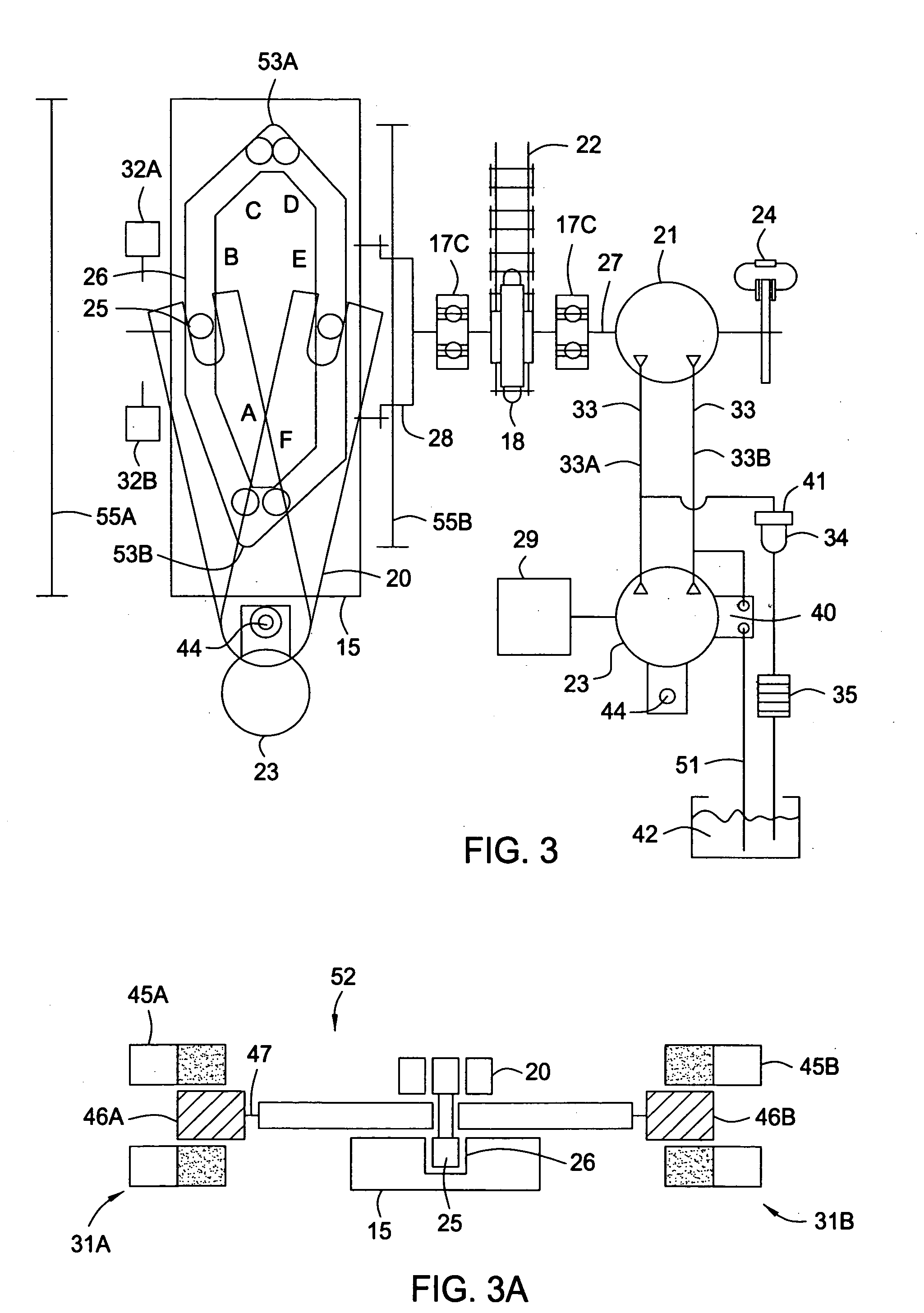
[0038] Embodiments of the present invention include a drive mechanism including a highly responsive hydraulic drive motor driven with a closed loop hydraulic circuit. The responsiveness of the hydraulic drive motor results because the closed loop hydraulic circuit works on both sides of the hydraulic drive motor to power one side of the motor and brake one side of the motor when there is a need to stop rotation of the hydraulic drive motor suddenly. Additionally, the hydraulic drive motor is highly responsive to speed changes because of the lack of revolving parts in the drive mechanism, as revolving parts in a mechanical drive mechanism are difficult to quickly reduce in speed or stop because of inertia.

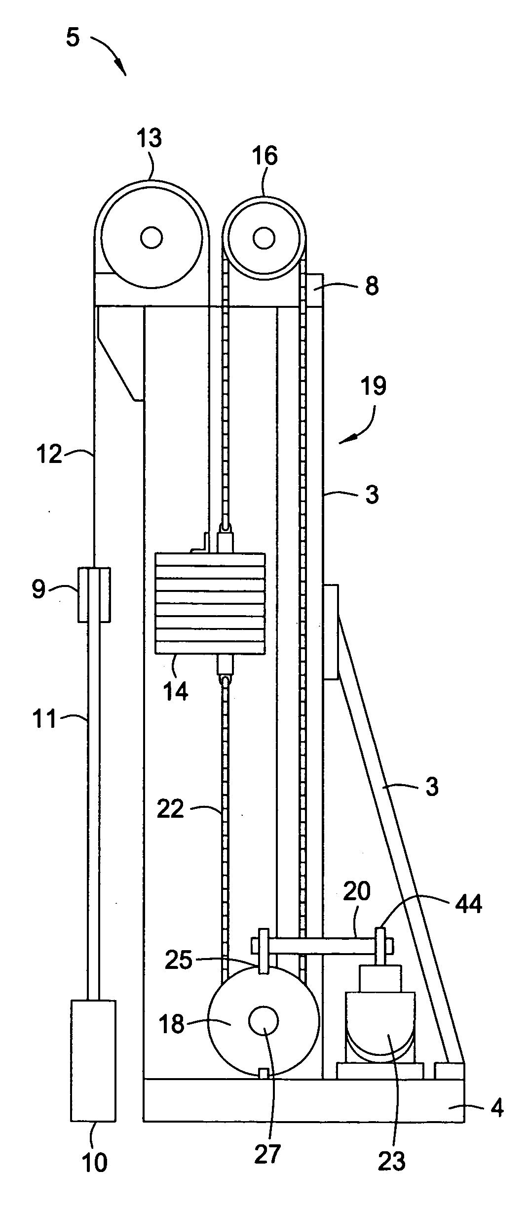
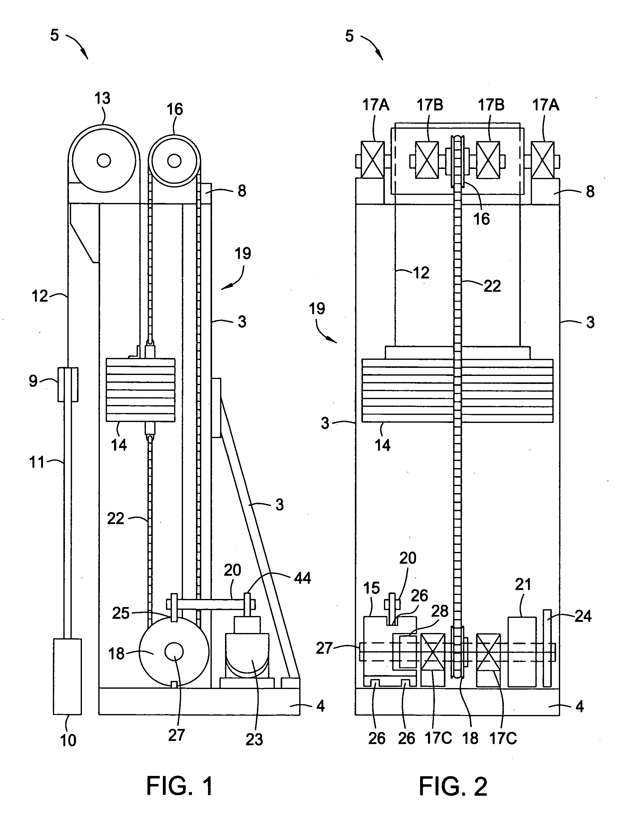
[0039]FIGS. 1 and 2 show side and front views, respectively, of a drive mechanism 5 used to drive a positive displacement pump (not shown) from a surface of a wellbore (not shown). The drive mechanism 5 is preferably disposed at least partially within a tower 19 having a base frame...


PUM


Abstract

Methods and apparatus for driving a positive displacement pump disposed within a wellbore are disclosed herein. Embodiments of the present invention provide a drive mechanism for driving the downhole positive displacement pump. In embodiments of the present invention, the positive displacement pump is hydraulically driven and mechanically counterbalanced. The drive mechanism may be mechanically or electrically controlled, or may be controlled by a combination of mechanical and electrical controls.

Description

BACKGROUND OF THE INVENTION [0001] 1. Field of the Invention [0002] Embodiments of the present invention generally relate to a reciprocating positive displacement pump utilized downhole within a wellbore to pump production fluid to a surface of the wellbore. More specifically, embodiments of the present invention relate to a drive mechanism for the downhole positive displacement pump. [0003] 2. Description of the Related Art [0004] To obtain hydrocarbon fluids from an earth formation, a wellbore is drilled into the earth to intersect an area of interest within a formation. Upon reaching the area of interest within the formation, artificial lift means is often necessary to carry production fluid (e.g., hydrocarbon fluid) from the area of interest within the wellbore to the surface of the wellbore. Some artificially-lifted wells are equipped with sucker rod lifting systems. [0005] Sucker rod lifting systems generally include a surface drive mechanism, a sucker rod string, and a downho...

Claims


Application Information

Patent Timeline
Patent Type & Authority Applications(United States)
IPC IPC(8): F04B23/08F04B35/04
CPCF04B47/04Y10S417/904
Inventor SMITH, NORRIS EDWARDBROOKS, ROBERT T.
Owner SMITH NORRIS EDWARD
Learn More