
System and method for propagating satellite TV-band, cable TV-band, and data signals over an optical network

a satellite tv and optical network technology, applied in the field of video, voice, data communication, can solve the problems of increasing reducing the cost of ftth and fttb architectures, and reducing the cost of hardware needed, so as to achieve efficient propagation and cost efficient

Inactive Publication Date: 2006-01-26
ENABLENCE USA FTTX NETWORKS
View PDF98 Cites 54 Cited by
  • Summary
  • Abstract
  • Description
  • Claims
  • Application Information

AI Technical Summary

Benefits of technology

[0011] The invention is a system and method for efficient propagation of data, cable television (TV)-band signals, and satellite TV-band signals over an optical fiber network. The system can permit a subscriber to receive both cable TV-band signals and satellite TV-band signals or either type. The system can permit small scale organizations, such as an apartment building with multiple subscribers, to offer data services and TV services in a very cost efficient manner.

Problems solved by technology

However, in the past, the cost of FTTH and FTTB architectures have been considered prohibitive.
While costs have generally declined for FTTH and FTTB architectures, small scale operators of FTTH and FTTB architectures usually find that the cost associated with hardware needed to support cable TV-band video programming over the FTTH / FTTB optical networks can be an impediment to enter the market.
In other words, the north side of a building cannot receive satellite signals because its satellite dish antennas would be unable to “see” or be positioned in a manner to have a direct line of sight with the satellites that are transmitting satellite TV-band signals to the earth.
Another problem exists for the small scale FTTH / FTTB operator who desires to offer video services from both cable TV-band suppliers and satellite TV-band suppliers.
Many conventional FTTH and FTTB architectures have not contemplated supporting video services originating from either cable TV-bands or satellite TV-bands or both.

Method used


Image

  • System and method for propagating satellite TV-band, cable TV-band, and data signals over an optical network
  • System and method for propagating satellite TV-band, cable TV-band, and data signals over an optical network
  • System and method for propagating satellite TV-band, cable TV-band, and data signals over an optical network

Examples


Embodiment Construction

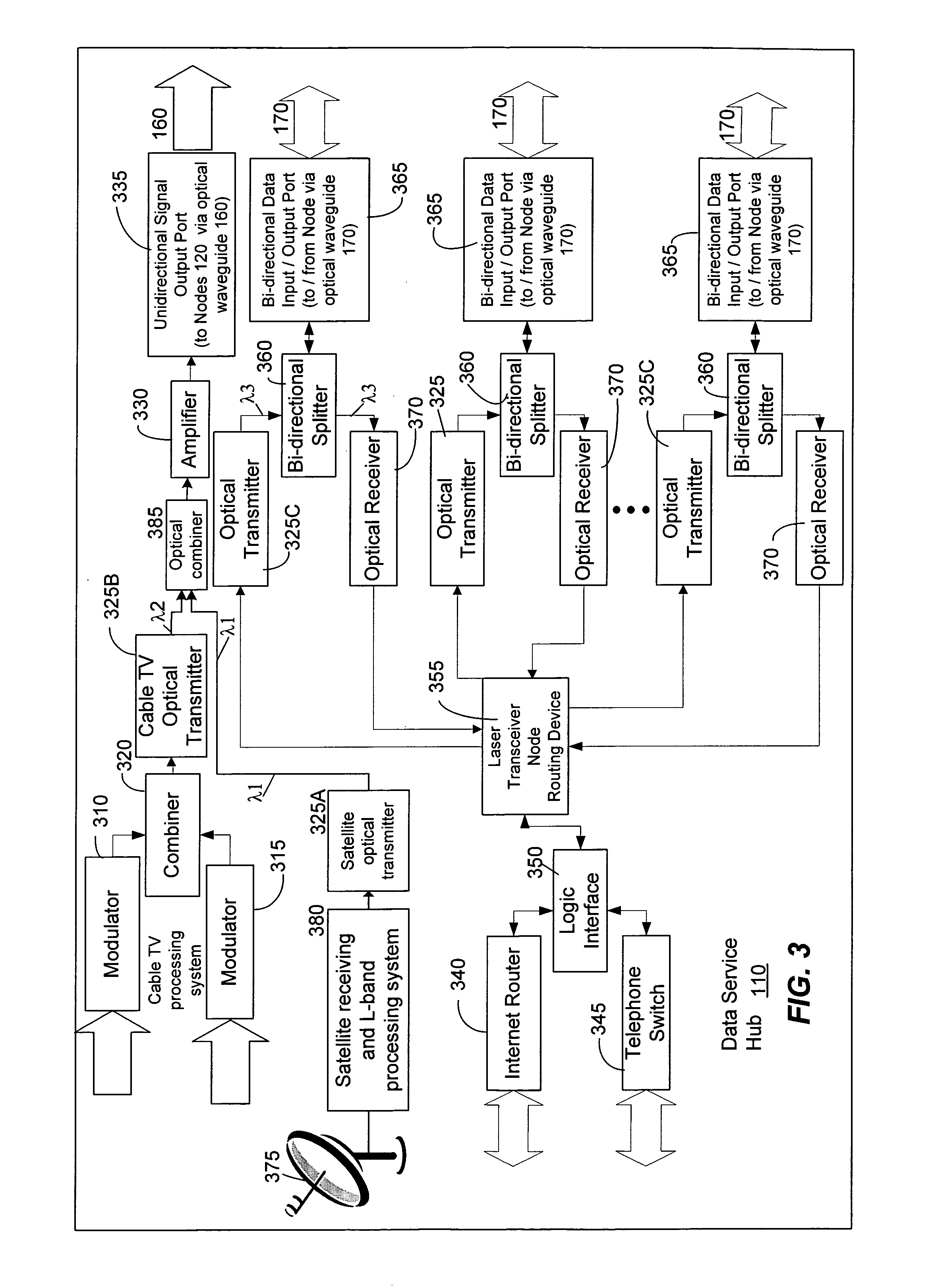
[0033] The invention may be embodied in hardware or software or a combination thereof disposed within an optical network. The optical network can include a data service hub, a laser transceiver node, and a subscriber optical interface. The data service hub can comprise a satellite antenna and a RF receiver for receiving satellite TV-band electrical signals. These electrical signals can be converted into the optical domain and then propagated over the optical network through optical waveguides to the subscriber optical interface. The subscriber optical interface can comprise an optical filter and a satellite analog optical receiver. The optical filter can separate the satellite TV-band optical signals having a first optical wavelength from other optical signals such as cable TV-band optical signals with a second optical wavelength and data optical signals with a third optical wavelength.

[0034] The satellite analog optical receiver can comprise a selector switch for selecting between...


PUM


Abstract

An optical network can include a data service hub, a laser transceiver node, and a subscriber optical interface. The data service hub can comprise a satellite antenna and a RF receiver for receiving satellite TV-band electrical signals. These electrical signals can be converted into the optical domain and then propagated over the optical network through optical waveguides to the subscriber optical interface. The subscriber optical interface can comprise an optical filter and a satellite analog optical receiver. The optical filter can separate the satellite TV-band optical signals having a first optical wavelength from other optical signals such as cable TV-band optical signals with a second optical wavelength and data optical signals with a third optical wavelength. The satellite analog optical receiver can further comprise various mechanisms for controlling access to the satellite TV-band signals.

Description

PRIORITY CLAIM TO PROVISIONAL AND NON-PROVISIONAL APPLICATIONS [0001] The present application claims priority to provisional patent application entitled, “METHOD FOR RECEIVING SATELLITE-BAND OR CABLE-TV BAND SIGNALS IN AN OPTICAL NETWORK,” filed on Jul. 2, 2004 and assigned U.S. application Ser. No. 60 / 584,957; the entire contents of which are hereby incorporated by reference. The present application also claims priority to Non-provisional patent application entitled, “SYSTEM AND METHOD FOR COMMUNICATING OPTICAL SIGNALS BETWEEN A DATA SERVICE PROVIDER AND SUBSCRIBERS,” filed on Jul. 5, 2001 and assigned U.S. application Ser. No. 09 / 899,410; the entire contents of which are incorporated by reference.TECHNICAL FIELD [0002] The invention relates to video, voice, and data communications. More particularly, the invention relates to a system and method for communicating satellite TV-band or cable-TV band (or both) signals and data signals from a data service provider to one or more subscr...

Claims


Application Information

Patent Timeline
IPC IPC(8): H04N7/20H04N7/173
CPCH04B10/25751H04J14/0298H04N7/22H04N21/2221H04N21/2383H04N21/2385H04N21/2665H04N21/42684H04N21/4436H04N21/6118H04N21/6143H04N21/6332H04N2007/1739H04J14/0232H04J14/0247H04J14/0252H04J14/0282H04N7/20
Inventor KENNY, JOHN J.WHITTLESEY, PAUL F.FARMER, JAMES O.
Owner ENABLENCE USA FTTX NETWORKS
Learn More