
Light emitting diode replacement lamp

a technology of light emitting diodes and replacement lamps, which is applied in the direction of lighting support devices, lighting and heating apparatuses with built-in power, etc., can solve the problems of considerable heat, waste, substantial current consumption, and leds having an extremely long life compared to incandescents

Active Publication Date: 2006-01-19
LEDVANCE LLC
View PDF1 Cites 200 Cited by
  • Summary
  • Abstract
  • Description
  • Claims
  • Application Information

AI Technical Summary

Benefits of technology

[0017] An additional embodiment to the present invention may include additional circuitry occupying the volume available. This circuitry may include the following: circuitry to allow remote control of lighting functions via an infrared or wireless device; circuitry to change the color of either or both of the (decorative) shade illumination and the direct illumination LEDs; circuitry that causes a time ...

Problems solved by technology

Because they use hot filaments, these products produce considerable heat, which is wasted, in addition to visible light that is desired.
These lights consume substantial current and dissipate considerable unwanted heat.
LEDs have an extremely long life compared to incandescent and halogen bulbs.
Moreover, unlike incandescent and halogen bulbs, LEDs are not shock-sensitive and can withstand large forces without failure, while the hot filament of an incandescent or halogen bulb is prone to rupture.
Too high an operating voltage causes premature failure, while too low an operating voltage or current reduces light output.
Furthermore, as the voltage to an incandescent and halogen light is reduced, its temperature drops, and so its internal resistance decreases, leading to higher current consumption, but without commensurate light output.
This is not easily accomplished using LEDs.
Halogen lights with their dichroic reflectors do this unintentionally, but ordinary incandescent lights employ external shades, not part of the light bulb, in a variety of artistic designs to make use of this otherwise misdirected light.

Method used


Image

  • Light emitting diode replacement lamp
  • Light emitting diode replacement lamp
  • Light emitting diode replacement lamp

Examples


Embodiment Construction

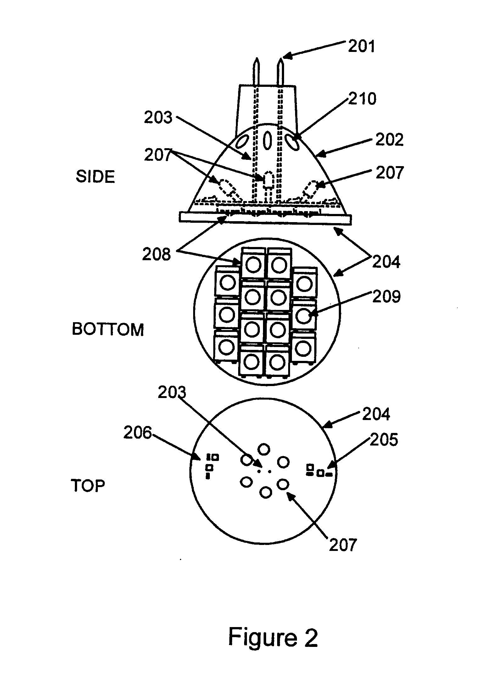
[0029] While this invention is susceptible to embodiment in many different forms, there are shown in the drawings, and will be described herein in detail, specific embodiments thereof with the understanding that the present disclosure is to be considered as an exemplification of the principles of the invention and is not to be limited to the specific embodiments described.

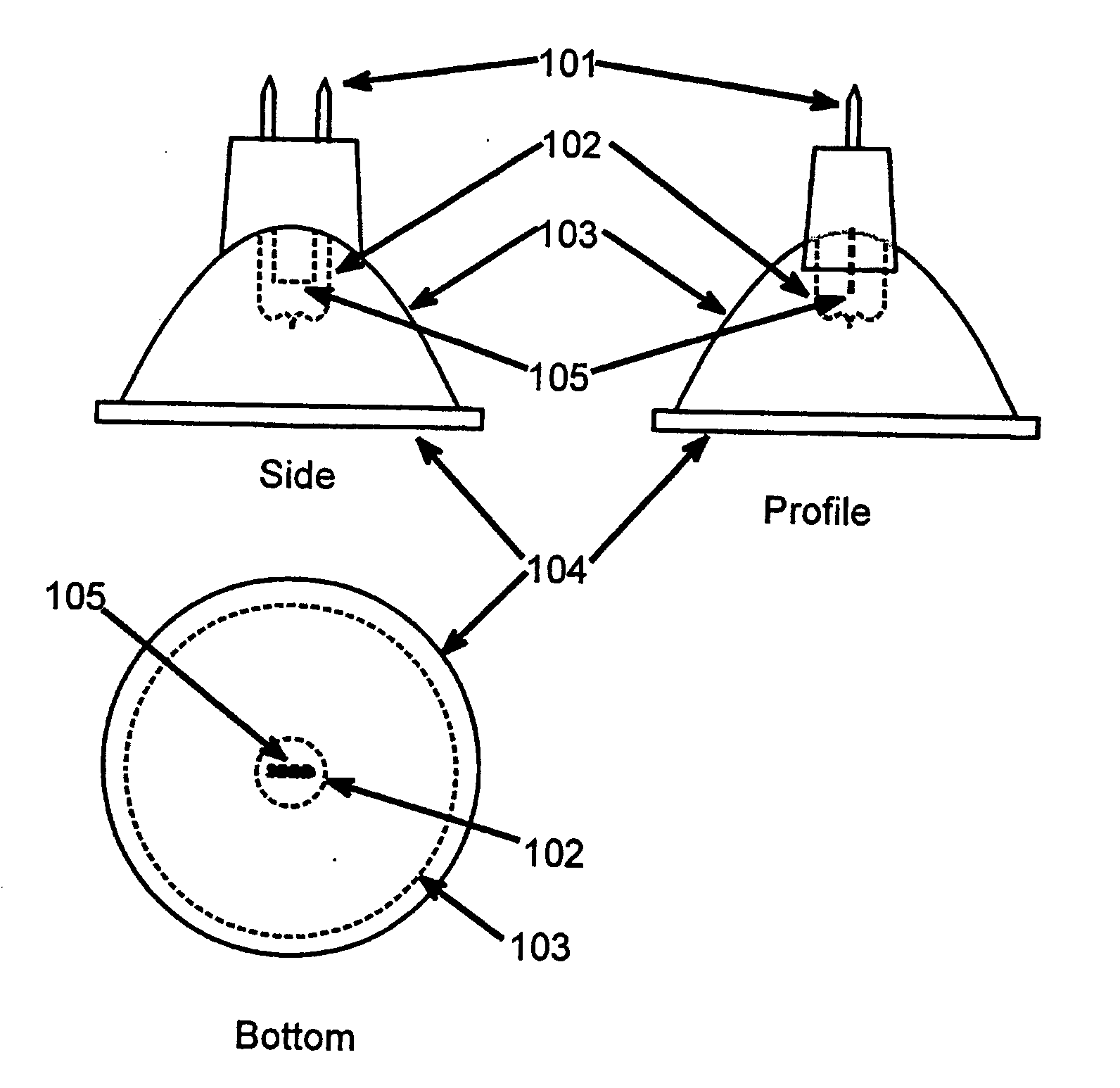
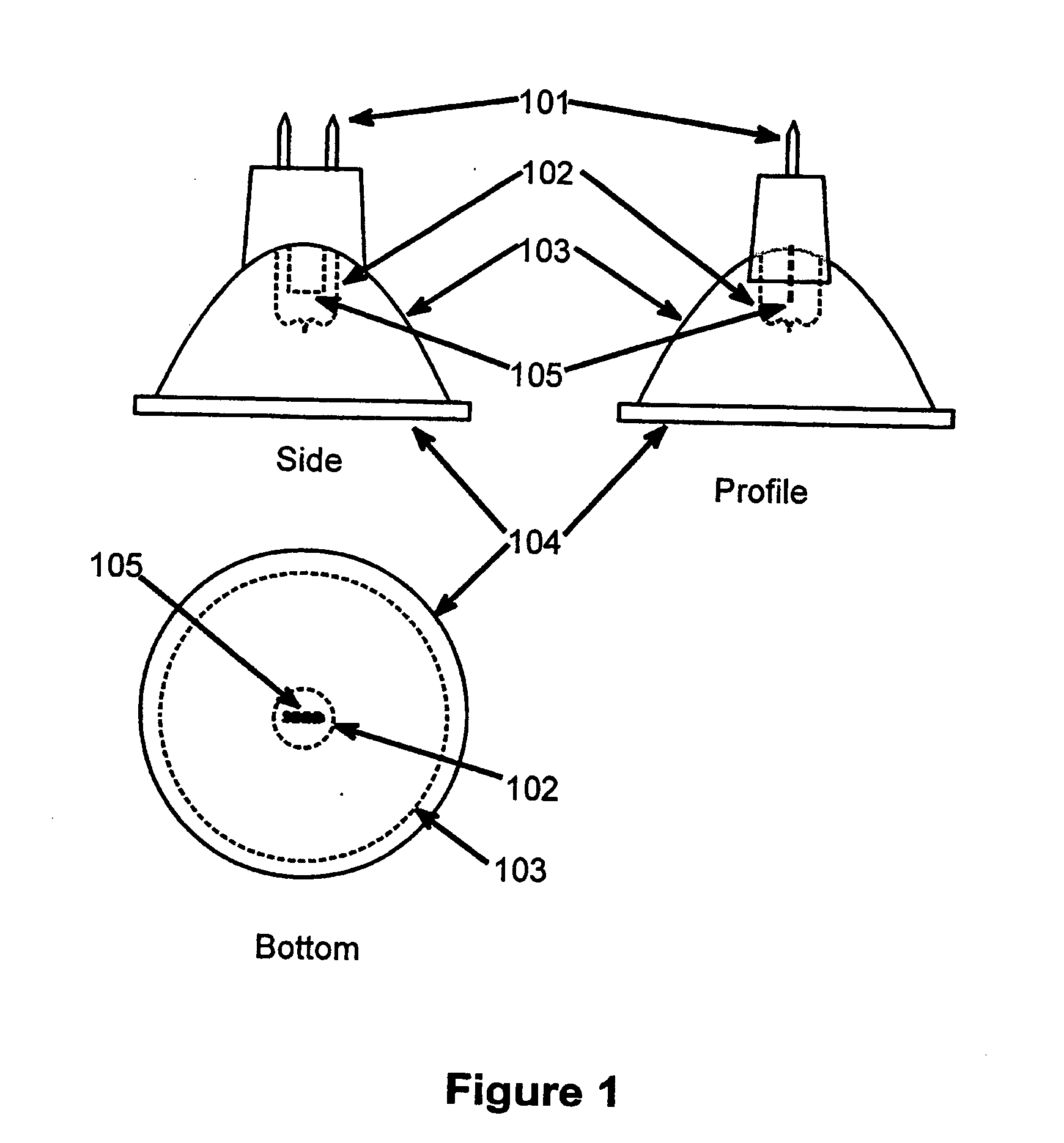
[0030]FIG. 1 illustrates an incandescent halogen type bulb commonly available. The features of this bulb have been derived from the operating characteristics implicit in the operation of these type illumination devices: they operate at high temperatures; they require an evacuated envelope separated from the hot filament; they emit large quantities of infrared radiation experienced by the user as heat; and they consume large quantities of electrical power. Nonetheless these devices are in common usage and fixtures and appliances have been constructed to accommodate the form, fit, and function of these bulbs. This p...


PUM


Abstract

The invention is a replacement for a conventional incandescent or halogen light bulb. Besides providing regular illumination, it has advantages over a conventional bulb while maintaining the bulb's decorative function, such as visual effects associated with the bulb's envelope or shade. The invention comprises a connector equivalent to a standard light bulb base, at least one light emitting diode (LED), and a driving circuit hosted on a module such as a printed circuit board and adapting the supply voltage to the requirements of the LED. Compensation for the effects of temperature may be included. The invention may also include other circuitry to support various enhanced features such as novel decorative features or control over the brightness, color, or other characteristics—all potentially varying over time or being controlled remotely.

Description

CROSS-REFERENCE TO RELATED APPLICATIONS [0001] U.S. Utility patent application Ser. No. 10 / 820,930; and [0002] U.S. Utility Provisional Patent Application 60 / 517,130, [0003] to which this patent application claims priority under 35 USC 119(e)BACKGROUND [0004] 1. Field of the Invention [0005] The present invention relates to a light emitting diode (LED) illumination device and method and more specifically to a light emitting diode, integrated with electronic circuitry that enables both an illumination function as well as a decorative function that can be varied by the user. [0006] 2. Description of Related Art [0007] Currently lighting applications are dominated by incandescent lighting products. Because they use hot filaments, these products produce considerable heat, which is wasted, in addition to visible light that is desired. Halogen based lighting enables filaments to operate at a higher temperature without premature failure, but again considerable non-visible infrared light is...

Claims


Application Information

Patent Timeline
IPC IPC(8): F21V33/00
CPCF21S9/022F21V29/83H01L25/0753H01L33/60H05B33/0815H05B33/0821H05B33/0851H05B33/0854Y02B20/383Y10S362/80F21Y2101/02F21V23/045F21K9/137F21K9/58H01L2224/48091F21V5/007F21V14/04F21V14/06F21V17/02H01L2924/00014H01L2924/00F21K9/233F21K9/65F21Y2107/90F21Y2115/10H05B45/10H05B45/20H05B45/3725H05B45/38H05B45/40H05B47/185Y02B20/30
Inventor CATALANO, ANTHONYHARRISON, DANIEL
Owner LEDVANCE LLC
Learn More