
Cold-cathode ionisation manometer having a longer service life due to two separate cathodes

a technology of ionization manometer and cold cathode, which is applied in the direction of measuring devices, instruments, particle separator tubes, etc., can solve the problems of limiting the usefulness of cold cathode ionization manometers, limiting the lower measuring range of manometers, and reducing the measuring accuracy, so as to improve the cold cathode measuring tube, improve the service life, and ensure the effect of good ionization

Inactive Publication Date: 2006-01-19
OTTO VONGUERICKE UNIV MAGDEBURG
View PDF7 Cites 20 Cited by
  • Summary
  • Abstract
  • Description
  • Claims
  • Application Information

AI Technical Summary

Benefits of technology

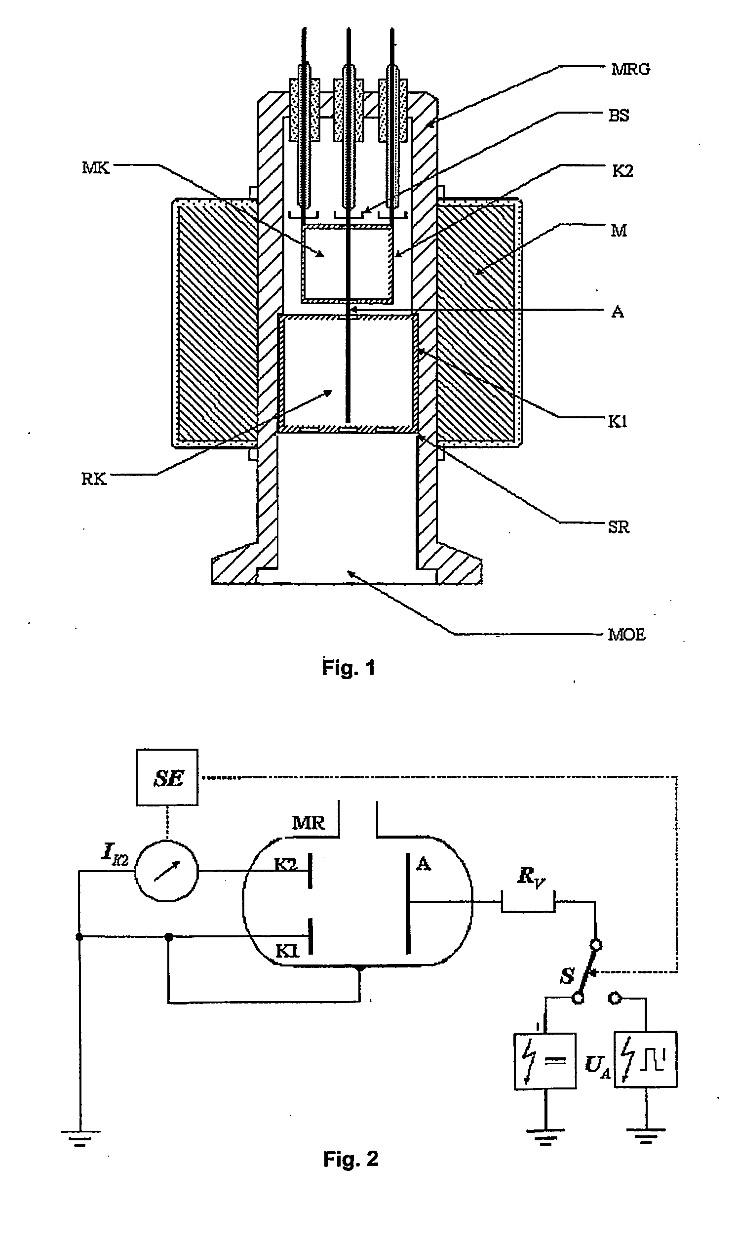
[0009] It is an object of the present invention from the very beginning to keep the rate of contamination of cold cathode ionization manometers low by an improved cold cathode measuring tube configuration and by a suitable measuring operation in order thereby to ensure a substantially longer service life of these measuring tubes. BRIEF SUMMARY OF THE INVENTION
[0011] While such double plasma arrangements in cold cathode ionization manometers have been known from former patent specifications (e.g. DE 1,648,689 or U.S. Pat. No. 5,568,053) the double discharge paths therein have always been used in a common measuring chamber (by separate magnetic field configurations) for the purpose of avoiding deviations in the pressure indications or for increasing the discharge current.
[0013] The discharge chamber in the area of the second cathode, which is arranged behind the measuring opening of the neighboring first cathode, functions as the measuring chamber proper. Only the discharge current flowing from this second discharge chamber is evaluated and made use of for pressure measurements. This particular double-plasma configuration offers the following advantage essential to the invention: The plasma fulgurating in the area of the first cathode and, hence, nearer to the vacuum chamber connecting to the measuring opening, is protecting the internal plasma fulgurating in the area of the second cathode and constituting the actual measuring position from interfering contaminations by condensing vapors. This prevents deposits in particular of undesirable carbon layers in the discharge chamber which is used for the actual measurements, which not only prevents shifting of any characteristic curve but also results in a noticeably reduced rate of contamination and, therefore, in a significantly longer service life of the measuring tube. This advantageous effect is augmented by the at least one opening in one of the facing front surfaces being dimensioned to form a predetermined flow resistance for contaminating gases.
[0015] For reducing the efficiency of the cathode atomization as a further main source of the contamination, the anode voltage, in a particularly advantageous embodiment of the invention, at pressures in excess of about 10−2 Pa is an alternating voltage the frequency of which is optimized in accordance with the geometric parameters of the measuring tube and the operating parameters. While the measuring tube in the entire lower vacuum range (<10−2 Pa) is driven by a constant positive anode voltage UA, at pressures above about 10−2 Pa it is advantageously operated by a sinusoidal or rectangular alternating voltage UA of constant frequency and constant amplitude. In this manner, the ions impinge on the cathodes only during the first half period, i.e. while the anode is positive relative to the cathodes, whereas during the second half period, when the anode is negative relative to the cathode, the ions are accelerated towards the anode and thereby can effectively clean themselves. In addition to the “self cleaning effect” thus achieved, the efficiency of the cathode atomization which contributes significantly to the process of contamination, particularly at higher vacuum pressures, is drastically reduced.

Problems solved by technology

In addition to the numerous advantages to be derived from the use of these manometers, these measuring instruments nevertheless suffer from the decisive disadvantage which at least in time significantly limits their usefulness.
With increasing service life, their measuring accuracy diminishes in consequence of contaminations of their measuring cells.
An applied operating voltage may lead to leakage currents which are superimposed upon the discharge current and thus significantly limit the lower measuring range of the manometer.
As a result of the described cathode pulverization, the useful life of the cathode is of limited duration.
Since as a rule the cathode material is stainless steel, released particles of the formed contamination layers may be aligned in the magnetic field and lead to short circuits.
The cracking products (usually layers of carbon) formed by these plasma-chemical reactions may also be deposited on electrode surfaces and there form surface layers which adversely affect the yield of their secondary electrons and which may shift characteristic curves and render an unstable indication of pressure.
In the least favorable condition it is even possible that the discharge is extinguished with an accompanying failure of the measuring tube.
Since as a result of the interference effects described supra the useful life of the measuring instruments is limited, all conventional commercial cold cathode ionization manometers are structured such that they may be disassembled easily for cleaning contaminated electrodes or for replacing them by new ones.
However, in order lastingly to ensure full efficiency of these vacuum gages, it is necessary to calibrate or clean the measuring tubes at regular intervals which always entails increased maintenance and costs.
Although the effect of the contamination of these measuring tubes and their consequences has been known from the time of their application in vacuum measuring technology there are, or have been, few, if any, promising approaches to its reduction.
Hence, the pressure indicated by them are likely to suffer from greater errors.

Method used


Image

  • Cold-cathode ionisation manometer having a longer service life due to two separate cathodes
  • Cold-cathode ionisation manometer having a longer service life due to two separate cathodes

Examples


Embodiment Construction

[0019] The housing MRG of the measuring tube consists of a tubular flange which is closed at the opening positioned opposite the measuring opening MOE (and its connecting flange to the measuring position). The closed side of the tubular flange contains three vacuum tight electrically well insulated conduits which are provided with a vaporization protection BS, one concentric one for the rod-shaped anode A and two eccentric ones for the second cathode K2 the discharge current of which is used for measuring purposes. Instead of one of the two measuring conduits for the second cathode K2, a bracket well insulated from the housing may be provided as a rigid support for the cathode K2. The two cathodes K1 and K2 are of drum or can-shaped configuration with substantially closed cap-like end surfaces. The second cathode Ka is positioned in the closed section of the housing MRG of the measuring tube and is secured in its position by suitable clamping connections which in turn are held by th...


PUM


Abstract

A cold cathode ionization manometer for measuring pressure in vacuum and operating on the inverse magnetron principle. For extending the service life of the manometer it is provided with two independently operating cathodes and a common anode mounted in a measuring tube. The first cathode is mounted at the inlet of the measuing tube and its discharge serves as a gas purification device which prevents the formation of contaminating layers by cracking and polymerizing hydrocarbons and other substances entering the measuring tube thereby protecting the second cathode and extending the overall service life of the manometer.

Description

BACKGROUND OF THE INVENTION [0001] 1. Field of the Invention [0002] The invention relates to a cold cathode ionization manometer for measuring pressure in a vacuum, operating in accordance with the inverse magnetron principle and used for detecting pressures in the fine, high and ultra-high vacuum range (preferably between 10−7 Pa and 1 Pa). [0003] 2. The Prior Art [0004] In ionization manometers of this type a spontaneous cold gas discharge is ignited by a high voltage between two unheated electrodes—the anode and the cathode—suitably arranged in the housing of a measuring tube. The ignition is maintained up to the smallest pressures by an additional magnetic field of sufficient field strength. The discharge current which flows during this time is dependent on the pressure over a very broad vacuum range and (usually) serves as a measure of the pressure. Known structures of cold cathode ionization manometers currently used commercially are the electrode configurations proposed by Pe...

Claims


Application Information

Patent Timeline
IPC IPC(8): G01L21/30G01L21/34H01J41/06
CPCH01J41/06G01L21/34
Inventor EDELMANN, CHRISTIANWILFERT, STEFAN
Owner OTTO VONGUERICKE UNIV MAGDEBURG
Learn More