Load bed lift-roof cover
- Summary
- Abstract
- Description
- Claims
- Application Information
AI Technical Summary
Benefits of technology
Problems solved by technology
Method used
Image
Examples
Embodiment Construction
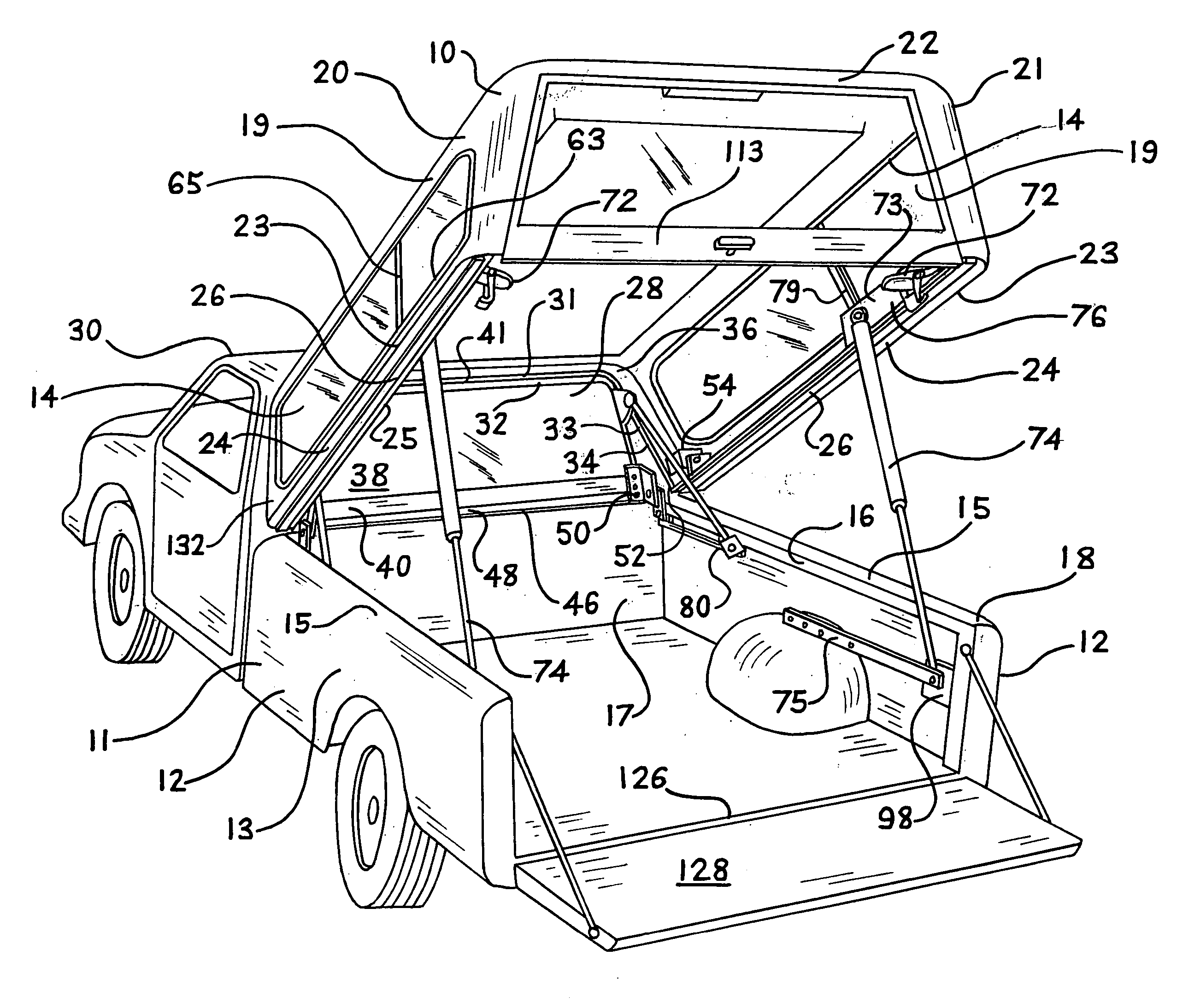
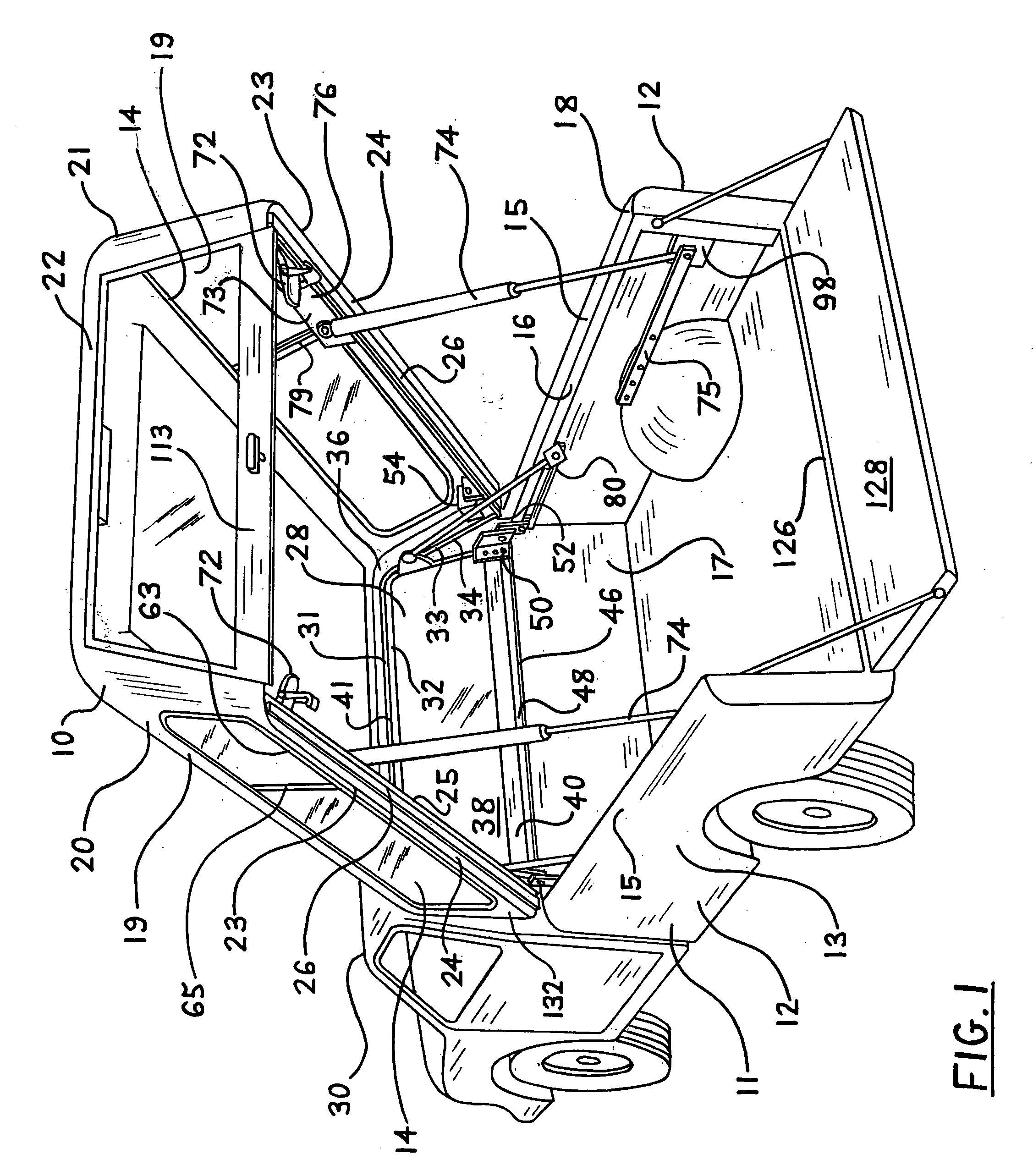
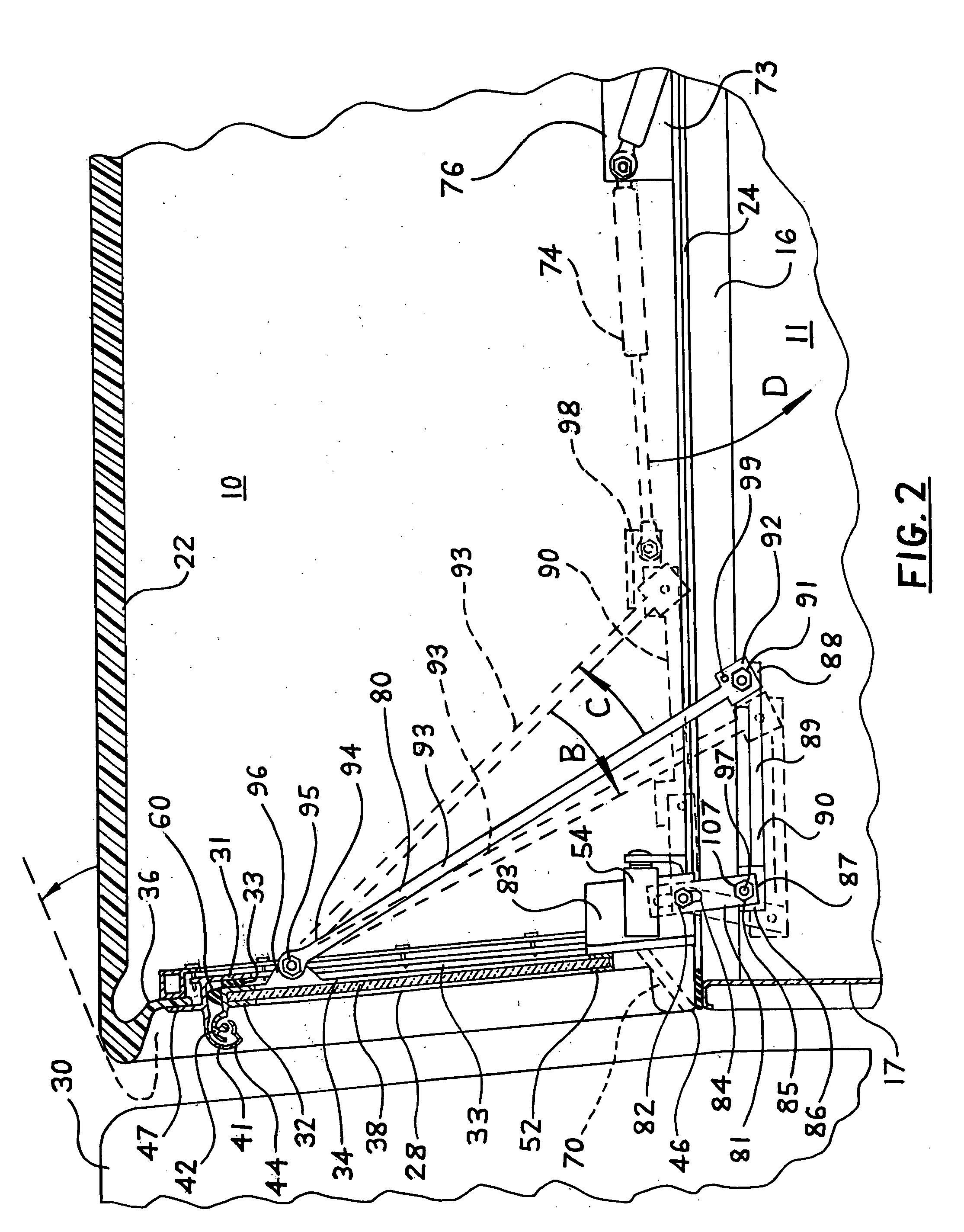
[0055] Referring to FIG. 1: The lift-roof cover 10 is mounted on a load bed 11 including side walls 12 fabricated so that the outside vertical surface 13 of the load bed wall 12 is continuous with the upper, substantially horizontal surface 15 of the wall 12 and the surface 15 likewise is continuous with an inside vertical flange 16 formed approximately at 90 degrees where it joins the upper surface 15, the flange 16 serving to add rigidity to the upper surface 15, as needed under vertical loading, and extending downward typically one to two inches. The flange 16 is fully accessible along most of the length of the load bed 11 between the load bed forward wall 17 and rear end 18. Side walls 19 at left and right sides 20, 21 respectively of a lift-roof structure 22 incorporate windows 14 and are joined at their lower edges 23 to substantially horizontal structural rails 24 which terminate along their length at an inner edge 25 almost directly above the load bed flanges 16. The rails 2...
PUM
 Abstract
Description
Claims
Application Information
 - R&D
- Intellectual Property
- Life Sciences
- Materials
- Tech Scout
- Unparalleled Data Quality
- Higher Quality Content
- 60% Fewer Hallucinations
Browse by: Latest US Patents, China's latest patents, Technical Efficacy Thesaurus, Application Domain, Technology Topic, Popular Technical Reports.
© 2025 PatSnap. All rights reserved.Legal|Privacy policy|Modern Slavery Act Transparency Statement|Sitemap|About US| Contact US: help@patsnap.com


