Helmet chin-strap harness structure

a chin-strap harness and harness structure technology, applied in helmet covers, headwear fastening, protective garments, etc., can solve the problems of disadvantages of this kind of conventional arrangement, general lack of quality in prior art chin-strap harness structures, and in its various forms

Inactive Publication Date: 2006-01-19
MJD INNOVATIONS
View PDF14 Cites 13 Cited by
  • Summary
  • Abstract
  • Description
  • Claims
  • Application Information

AI Technical Summary

Benefits of technology

[0010] The releasable length-interconnection mechanism which is most often supplied for coupling the usual two chin-strap elements is (a) typically quite bulky, (b) normally offset to one side of the chin and jaw when the chin-strap elements are coupled for use (see for example what is illustrated in the mentioned '829 patent), and (c) notably easily breakable. Its presence, in addition to being often quite uncomfortable, in that it bears as a “protrusion / enlargement” against one side of the face, results (a) in significant non-bilateral symmetry in overall harness disposition and performance, and, relatedly (b), in appreciable non-uniformity with respect to flexibilities and performance responses of the two lateral sides of a chin-strap harness because of the introduced, nonflexible rigidity which exists in the interconnect mechanism per se.
[0011] Another important drawback regarding prior art helmet harness structures is that they may enhance springiness in the manner in which an associated helmet system engages a wearer's head. Contrary to the long-standing, conventional-approach belief that springiness is an asset in handling shock cushioning, it is actually a serious and dangerous detriment. It amplifies rather than moderates a shock event. A good illustration of this problem of enhancement is found in the above-referred-to '829 patent which includes a pair of rigid and springy fixed (nominally) angular side members to which a chin-strap unit is attached.
[0015] Other features and advantages, such as structural simplicity, the absence of anything which might introduce, or contribute to springiness into the cooperative behavior of the invention with a helmet shell, and ease of use with a wide variety of helmets, will also become clearly apparent as the description of this invention now unfolds. DESCRIPTION OF THE DRAWINGS

Problems solved by technology

This quality is generally lacking in conventional prior art chin-strap harness structures, wherein, for example, laterally offset, laterally “unbalanced” rigid-body, strap-connection hardware, typically associated with a chin-strap unit per se, is employed.
This quality is also generally lacking in prior art structures, especially where rigid-body, strap-connection hardware of the type generally mentioned just above is employed, and / or where the point of connection between the effective lateral end of a chin-strap unit per se is anchored in a fixed-position manner to the usual pair of lateral strap, or strap-like, structures which typically anchor directly to the shell of a helmet.
The disadvantages of this kind of conventional arrangement, in its various forms (with rigid or flexible side-strap sub-components), are numerous.
To begin with, proper positional placement of that portion of the chin-strap which is intended to center upon and engage the chin is notably difficult to achieve, particularly in the situations where flexible fabric-like side straps are involved.
Adjustments to accomplish “load-balanced” centering are often quite challenging.
Fixedness of the locations where the outer ends of chin-strap elements connect to the two, lateral side-strap sub-components contributes both to this centering problem, and to the fact that the two pre-fixed-length elongate portions of such sub-components rarely share equally in tension load-bearing when a chin-strap is tightened against a wearer's chin.
In point of fact, one or the other of these fixed-length portions in each side strap is often quite slack.
Such a condition leads either (a) to helmet instability on the head, (b) to strange angular “cocking” of a helmet on the head in a manner which, because of conventional design, as distinguished from that of the present invention, laterally imbalances load-sharing in a helmet harness structure, and thus undesirably imbalances load-cushioning for the head, or (c) to both.
Adjustment to correct this kind of condition, and to keep all parts of a helmet, including the importantly cooperating chin-strap substructure and shell-internal, load-cushioning structure (usually shock-absorbing pads), properly shock-absorbingly positioned relative to one another, and especially so when the associated helmet may be cocked at an “odd angle” on the head, often is just not possible because of the precommitted fixed (defined) lengths of the side-strap sub-components
Its presence, in addition to being often quite uncomfortable, in that it bears as a “protrusion / enlargement” against one side of the face, results (a) in significant non-bilateral symmetry in overall harness disposition and performance, and, relatedly (b), in appreciable non-uniformity with respect to flexibilities and performance responses of the two lateral sides of a chin-strap harness because of the introduced, nonflexible rigidity which exists in the interconnect mechanism per se.
Another important drawback regarding prior art helmet harness structures is that they may enhance springiness in the manner in which an associated helmet system engages a wearer's head.
Contrary to the long-standing, conventional-approach belief that springiness is an asset in handling shock cushioning, it is actually a serious and dangerous detriment.
Another issue presented by the '829 patent structure is that the specific force carried in each “leg” of each of the rigid, springy side members can tend to try to shift the point of three-way intersection existing between the other leg in that side member and the associated, connected of the chin-strap unit.

Method used


Image

  • Helmet chin-strap harness structure
  • Helmet chin-strap harness structure
  • Helmet chin-strap harness structure

Examples


Embodiment Construction

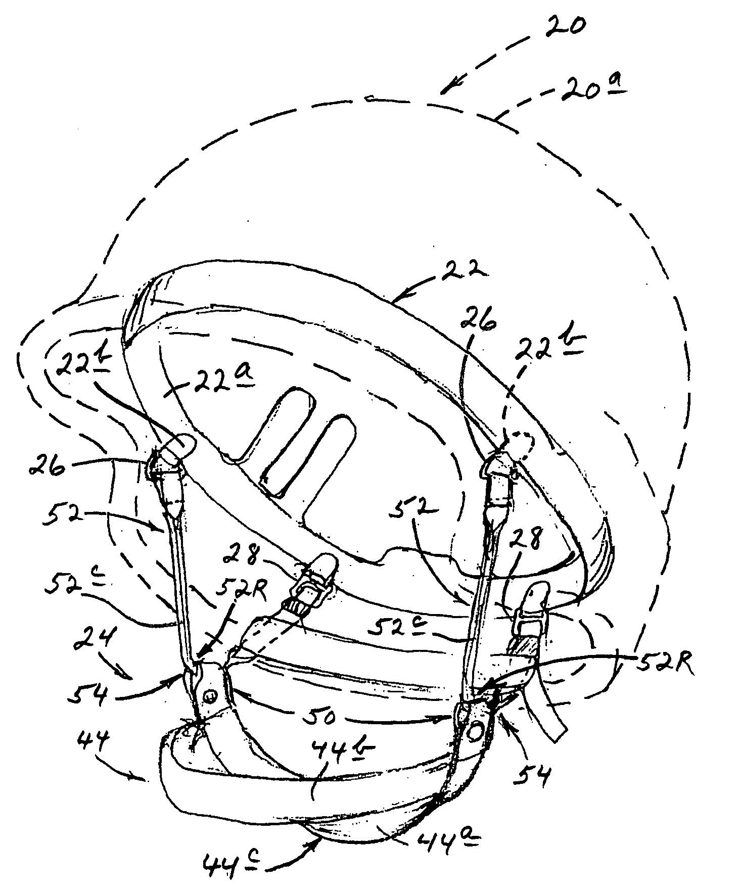
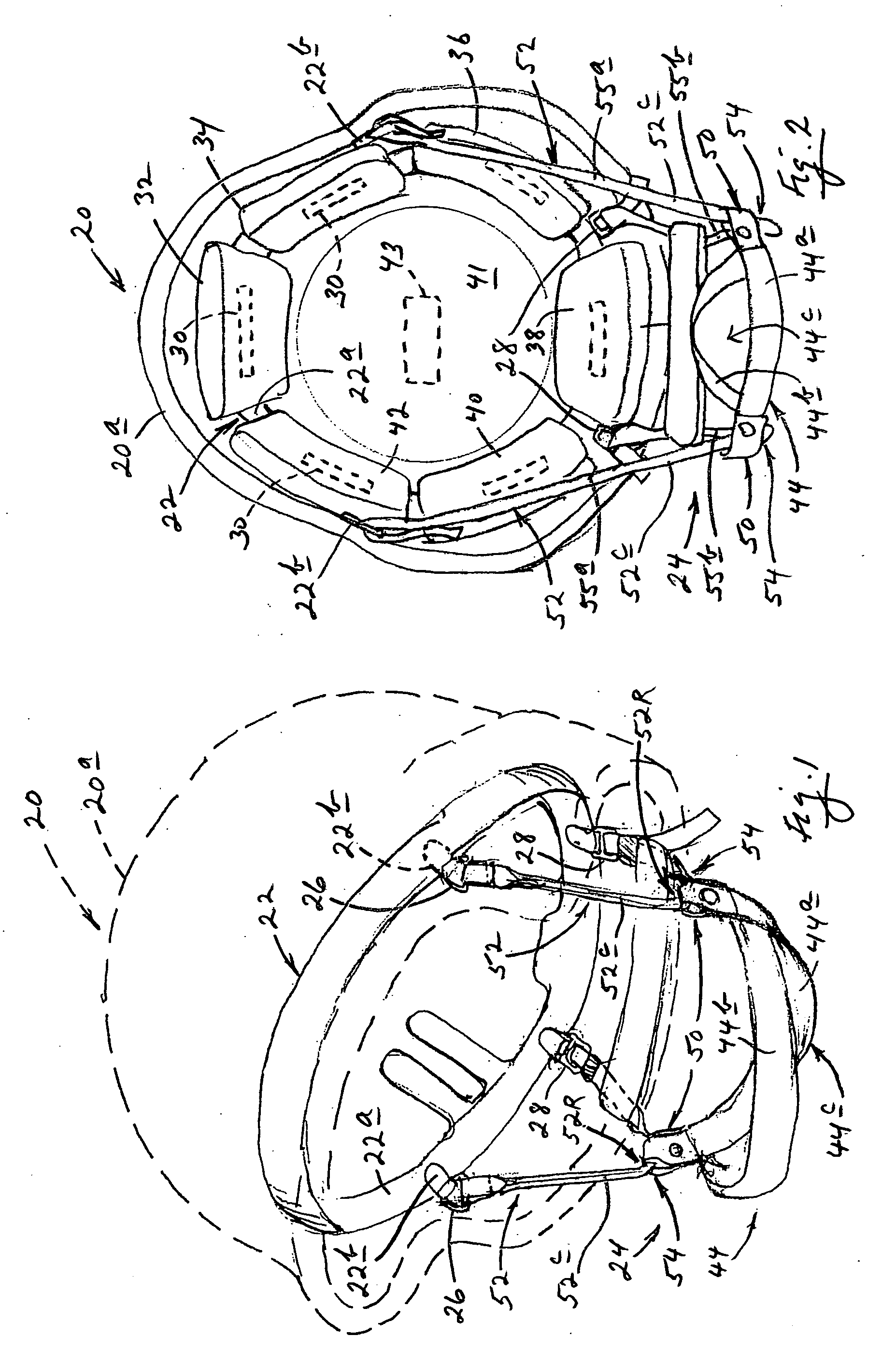
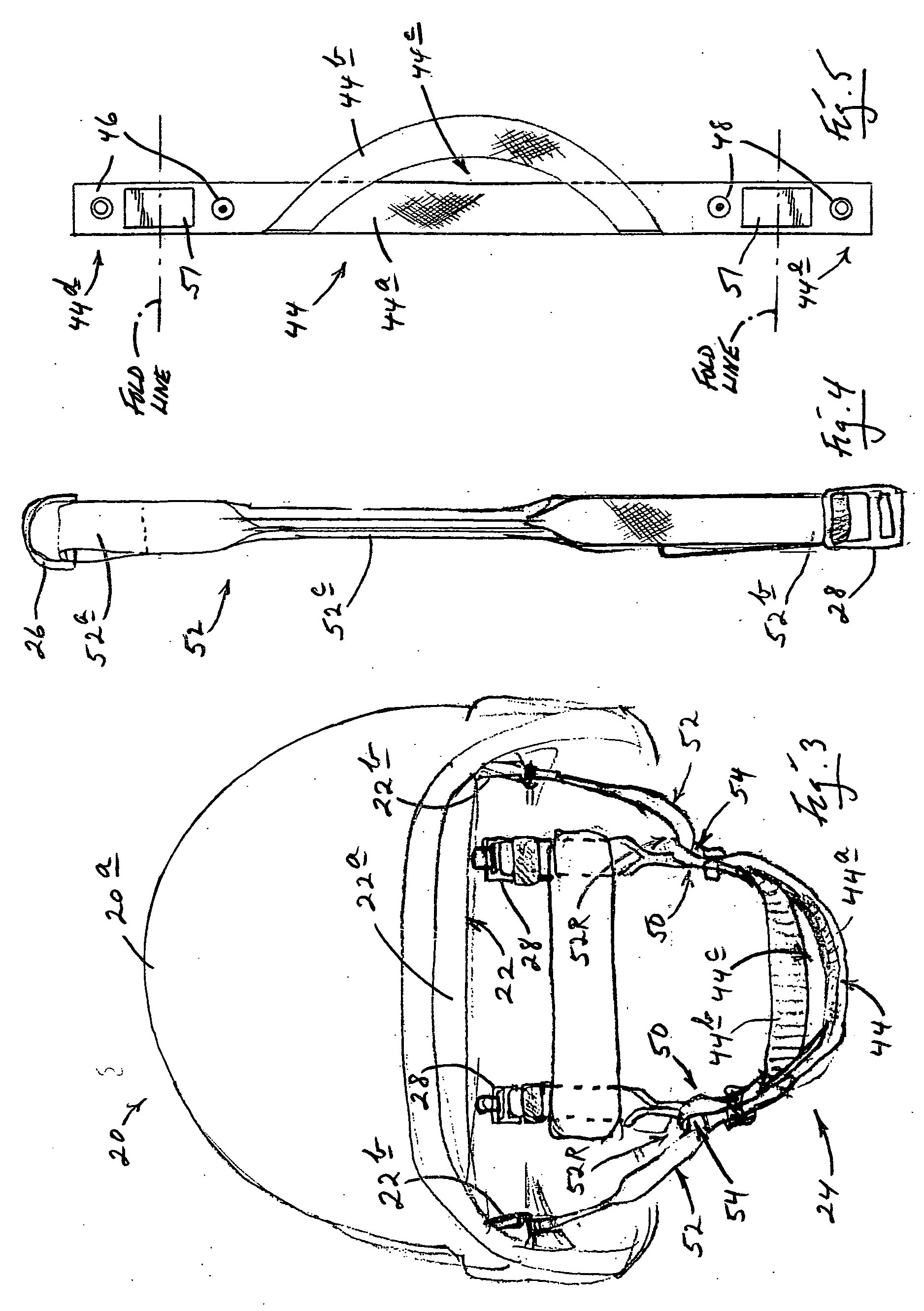
[0023] Beginning with attention directed to FIGS. 1-3, inclusive, in the drawings, shown generally at 20 is a military helmet having a shell 20a, on the inside of which, in the particular helmet illustrated herein, is an appropriately anchored, wrap-around suspension, or suspension frame, 22 made, for example, in accordance with the teachings of U.S. Pat. No. 6,681,402 B2, issued Jan. 27, 2004 for “Helmet Liner Suspension Structure”, the content of which is hereby incorporated herein by reference. Suspension 22 is employed, as will be explained shortly, to support the harness structure of the present invention, as well as a head-cushioning pad system. It should be understood that while various attachments are illustrated and described herein in the context of the presence of suspension 22, the use of such a suspension is not required by, or part of, the present invention, and all such attachments could be made differently, as for example, directly to the shell of a helmet, such as t...


PUM


Abstract

Helmet chin-strap harness structure including a pair of bilaterally symmetric, bilaterally equi-flex, non-rigid, fabric-strap-like, substantially mirror-image, flexible lateral elements which define opposite sides for the harness structure, and a bilaterally symmetric chin-strap substructure having laterally opposite sides releasably attachable for fore-and-aft translational sliding on the two lateral elements.

Description

CROSS-REFERENCE TO RELATED APPLICATION [0001] This patent application claims priority to prior-filed, co-pending U.S. Provisional Patent Application Ser. No. 60 / 587,888 filed Jul. 14, 2004, for “Helmet Chin-Strap Suspension Harness”. The entire disclosure content of this prior-filed provisional application is hereby incorporated herein by reference.BACKGROUND AND SUMMARY OF THE INVENTION [0002] This invention relates to a novel self-load-balancing chin-strap harness structure (or chin-strap system) for use in a protective, safety helmet—a kind of nominally unconstrained, “self-seeking” structure which addresses a number of significant disadvantages found in conventional harness structures of this general character. As will be seen, the concept “nominally unconstrained” refers to the fact that the structure and implementation of this invention include almost nothing in the way of rigidly configured, non-moveably anchored (at least with respect to certain appropriate degrees of freedo...

Claims


Application Information

Patent Timeline
IPC IPC(8): A63B71/10
CPCA42B3/08
Inventor DENNIS, MICHAEL R.PAASCHE, GERHARD
Owner MJD INNOVATIONS
Why Eureka
Try Eureka