
Disaster recovery processing method and apparatus and storage unit for the same

a technology of disaster recovery and processing method, applied in data processing applications, fault response, instruments, etc., can solve the problems of low db modification ratio, low loss of the modified contents of the transaction that has been completed in the main site in the remote site, etc., to achieve the effect of reducing the i/o load on the db disk, reducing the db modification ratio, and high db modification ratio

Active Publication Date: 2006-01-12
HITACHI LTD +1
View PDF26 Cites 118 Cited by
  • Summary
  • Abstract
  • Description
  • Claims
  • Application Information

AI Technical Summary

Benefits of technology

[0017] A first object of the present invention is to provide a technique in which the possibility that modification contents of transactions that have been completed in a main site are lost in a remote site is low, when executing processing in another information processing apparatus, or a program or an object that conducts its processing, in response to occurrence of a failure or a predetermined condition, or a request.
[0018] A second object of the present invention is to provide a technique in which the possibility that modification contents of transactions that have been completed in a primary system are lost in a secondary system is low.
[0019] A third object of the present invention is to provide a technique in which the performance degradation in the primary system can be reduced.
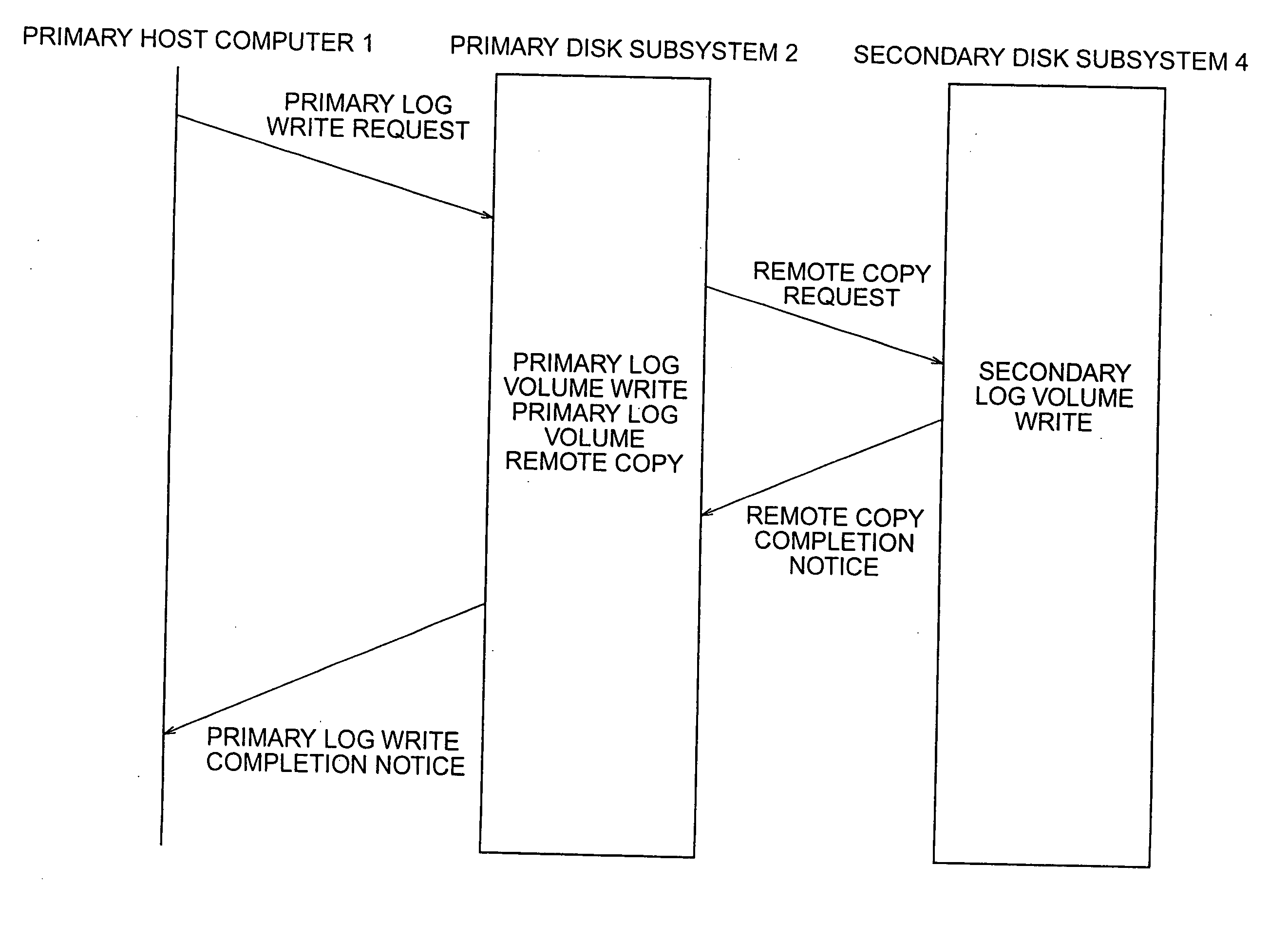
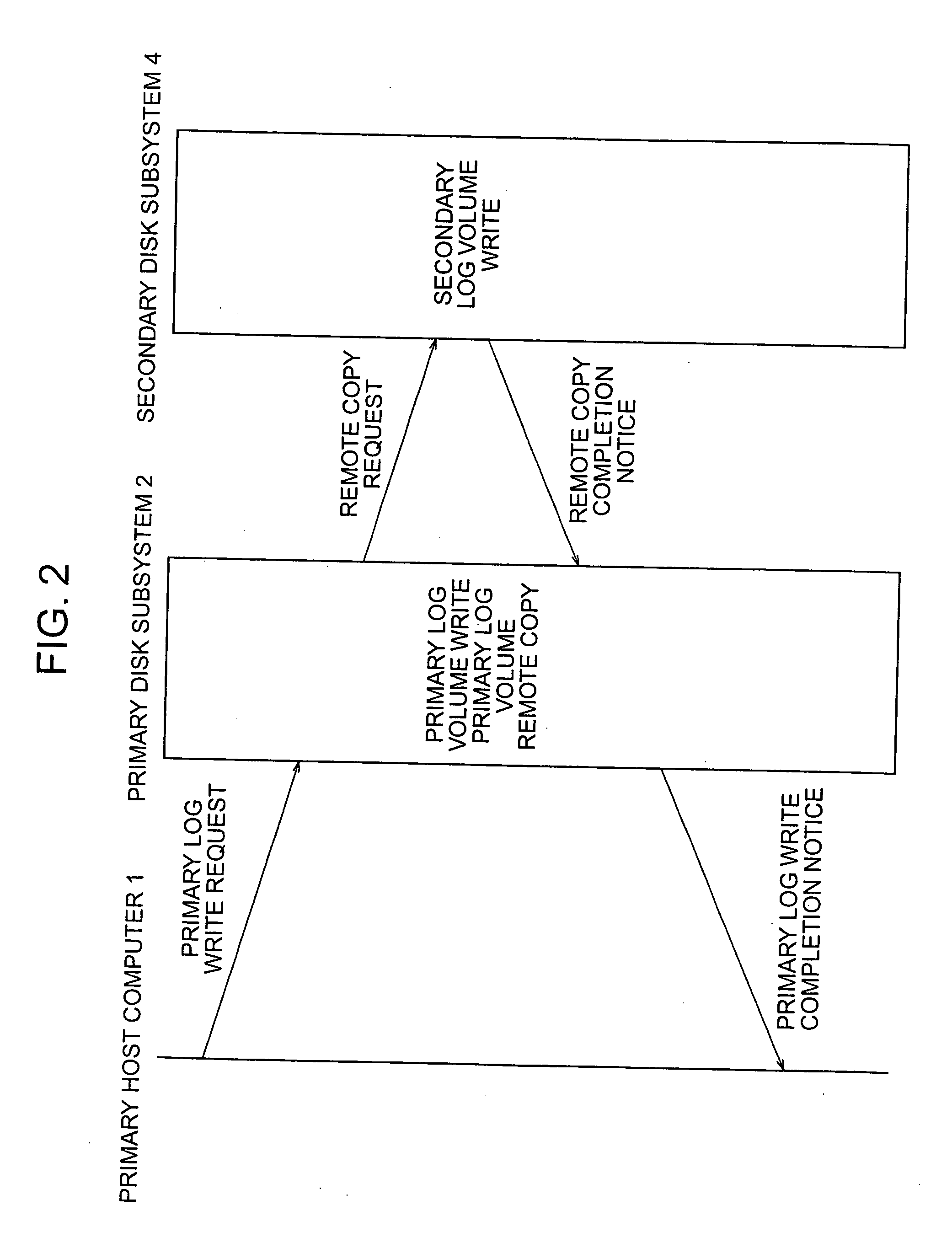
[0029] In business processing having a high DB modification ratio, the I / O load on the DB disk becomes high as compared with the log disk. On the other hand, transactions to be recovered in the secondary system depend on the information on the log disk. Therefore, it becomes possible to prevent modification contents of transactions completed in the primary system from being lost by conducting synchronous copy on the information on the log disk, and it becomes possible to construct a disaster recovery system reduced in performance degradation in the primary system by conducting asynchronous copy on the information on the DB disk.
[0030] According to the disaster recovery system of the present embodiment, log information is modified by synchronous writing and database data and status information are modified by asynchronous writing, when writing to the secondary system is requested, as heretofore described. Therefore, the contents of modification in transactions completed in the primary system are prevented from being lost in the secondary system. It is possible to construct a disaster recovery system reduced in performance degradation in the primary system.

Problems solved by technology

If in the conventional database management system (or computer system or information processing system, where a database management system is taken as an example) the log and DB (where a database is taken as an example, but data stored to be used for processing may also be used) are transferred to the remote site in synchronism with the main site, the possibility that modification contents of transactions that have been completed in the main site are lost in the remote site is low.
Since the log and DB are transferred synchronously, there is a problem that the performance in the main site is degraded as compared with the case where such a configuration is not adopted.
If in the conventional database management system the log and DB are transferred to the remote site asynchronously, then the performance degradation in the main site is slight, but there is a problem that modification contents of transactions that have been completed in the main site are sometimes lost in the remote site.

Method used


Image

  • Disaster recovery processing method and apparatus and storage unit for the same
  • Disaster recovery processing method and apparatus and storage unit for the same
  • Disaster recovery processing method and apparatus and storage unit for the same

Examples


Embodiment Construction

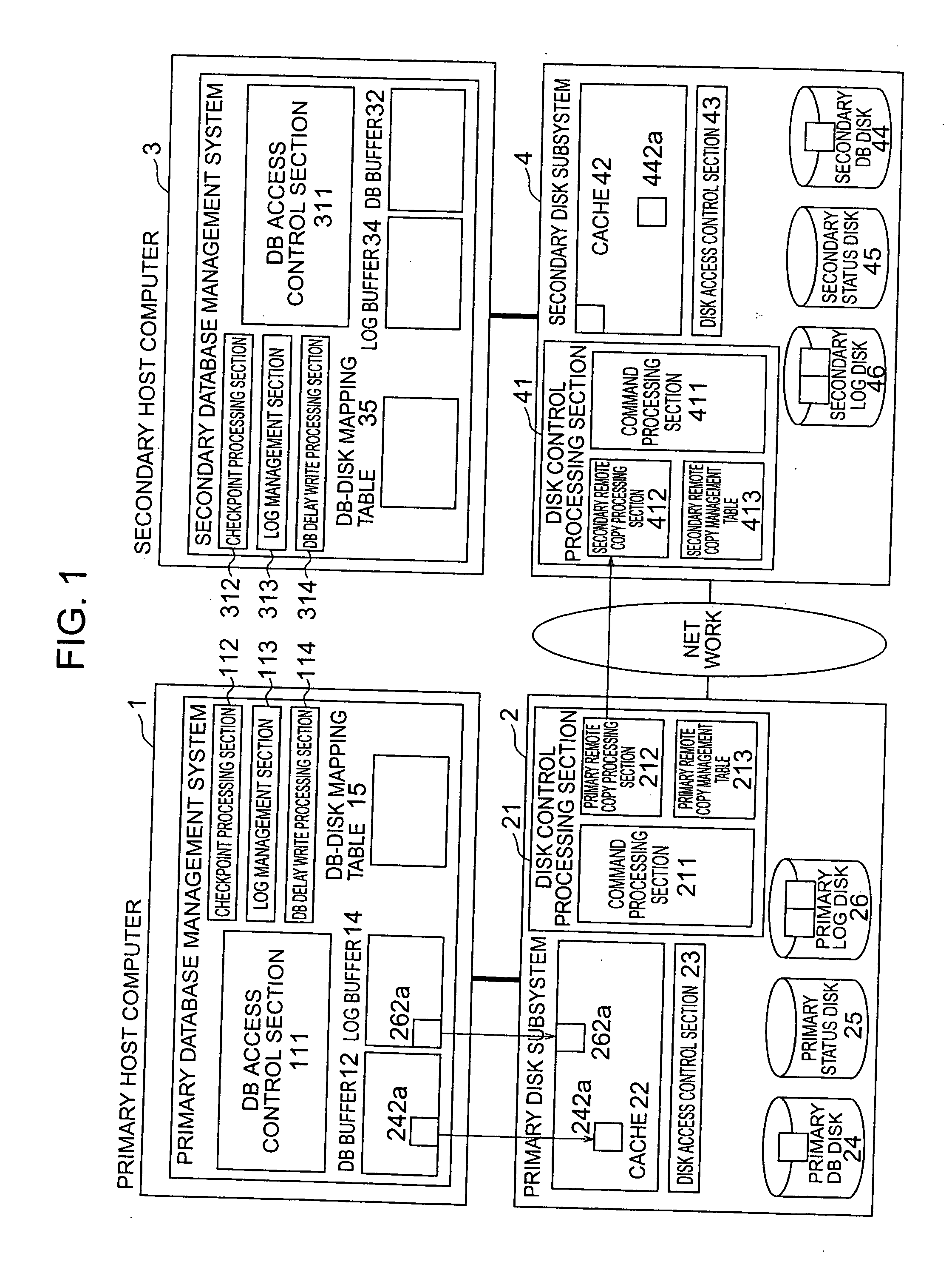
[0043] Hereafter, a system of an embodiment in which upon a write request to a secondary system log information is updated by synchronous writing and database data and status information are modified by asynchronous writing will be described.

[0044]FIG. 1 is a diagram showing a system configuration of the present embodiment. As shown in FIG. 1, a primary host computer 1 (which may be implemented by using a computer, an information processing apparatus, or a program or an object capable of conducting the processing) includes a DB access control section 111 (hardware, a program, or an object capable of conducting the processing), a checkpoint processing section 112 (hardware, a program, or an object capable of conducting the processing), a log management section 113 (hardware, a program, or an object capable of conducting the processing), and a DB delay write processing section 114 (hardware, a program, or an object capable of conducting the processing).

[0045] The DB access control s...


PUM


Abstract

A technique capable of constructing a disaster recovery system reduced in performance degradation of a primary system is provided. The technique includes a step of conducting synchronous writing of log information into a secondary storage subsystem in a secondary system when a write request received from a host computer is a write request of log information, a step of temporarily storing a write request and conducting asynchronous writing into the secondary storage subsystem when the received write request is a write request of database data or status information, a step of modifying log information, data in a database area, and status information in the secondary storage subsystem according to contents of a write request received from a primary storage subsystem, and a step of recovering the database area according to contents of log information in a location indicated by the status information.

Description

[0001] The present application is a continuation of application Ser. No. 10 / 650,842, filed Aug. 29, 2003, the contents of which are incorporated herein by reference.BACKGROUND OF THE INVENTION [0002] The present invention relates to a technique for executing processing in another information processing apparatus, or a program or an object that conducts its processing, in response to occurrence of a failure or a predetermined condition, or a request. [0003] For conventional database management systems (or computer systems or information processing systems), there is a technique of placing a plurality of replications in a plurality of geographically distributed sites (computers or information processing apparatuses) by way of precaution against failures, i.e., the so-called disaster recovery technique, data of a certain site are stored in other geographically separated sites as replications. In the case wherein a failure is caused by a disaster or the like in a certain site, business ...

Claims


Application Information

Patent Timeline
Patent Type & Authority Applications(United States)
IPC IPC(8): G06F12/00G06F3/06G06F11/14G06F11/20
CPCG06F11/2074Y10S707/99953G06F11/2076
Inventor KAWAMURA, NOBUOYAMAGUCHI, KOTAOEDA, TAKASHI
Owner HITACHI LTD
Learn More