Exhaust manifold for a vehicle

a technology for exhaust manifolds and vehicles, applied in the direction of engines, mechanical apparatus, machines/engines, etc., can solve the problems of excessive mounting space for conventional exhaust manifolds, and the inadequacies of conventional exhaust manifolds

Inactive Publication Date: 2006-01-12
HYUNDAI MOTOR CO LTD +1
View PDF12 Cites 2 Cited by
  • Summary
  • Abstract
  • Description
  • Claims
  • Application Information

AI Technical Summary

Benefits of technology

[0012] Embodiments of the present invention provide an exhaust manifold for a vehicle having non-limiting advantages employed to all vehicles, regardless of whether an engine compartment thereof is small or not.

Problems solved by technology

However, in an aspect of a layout, the conventional exhaust manifold has a problem of requiring excessive mounting space.
The first, second, third, and fourth exhaust pipes, the first and second connecting pipes, and the collecting duct consume excessive volume of an engine compartment, and therefore, such a conventional exhaust manifold is not appropriate for a vehicle that has a small engine compartment.

Method used


Image

  • Exhaust manifold for a vehicle
  • Exhaust manifold for a vehicle
  • Exhaust manifold for a vehicle

Examples


Embodiment Construction

[0024] An embodiment of the present invention will hereinafter be described in detail with reference to the accompanying drawings.

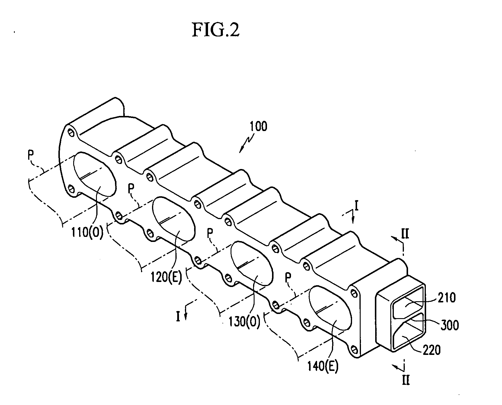
[0025] As shown in FIG. 2, an exhaust manifold for a vehicle according to an embodiment of the present invention includes a monolithically formed manifold body 100. First and second exhaust passages 210 and 220, and a plurality of runners O and E are formed inside the manifold body 100. The plurality of runners O and E are configured and dimensioned to be respectively connected to a plurality of exhaust ports P of an engine. The first exhaust passage 210 communicates with at least one of the plurality of runners (refer to the reference symbol O), and the second exhaust passage 220 communicates with the remnant of the plurality of runners (refer to the reference symbol E).

[0026] According to an embodiment of the present invention, forming the runners does not necessitate separate pipes. That is, the runners O and E can be formed as a consequence of fabri...


PUM


Abstract

An exhaust manifold for a vehicle includes a plurality of runners respectively connected to a plurality of exhaust ports of an engine; a first exhaust passage communicating with at least one of the plurality of runners; and a second exhaust passage communicating with a remnant of the plurality of runners, wherein the first and second exhaust passages, and the plurality of runners are formed inside a monolithic manifold body.

Description

CROSS REFERENCE TO RELATED APPLICATIONS [0001] This application claims priority of Korean Application No. 10-2004-0052433, filed on Jul. 6, 2004, the disclosure of which is incorporated herein by reference. FIELD OF THE INVENTION [0002] The present invention relates to an exhaust system of a vehicle. More particularly, the present invention relates to an exhaust manifold for a vehicle. BACKGROUND OF THE INVENTION [0003] Generally, as shown in FIG. 1, an exhaust system of a vehicle is for exhausting a gas from cylinders, and includes an exhaust manifold 1 and a muffler 2. [0004] Such a conventional exhaust manifold 1 includes a first exhaust pipe 11, a second exhaust pipe 12, a third exhaust pipe typically 13 and a fourth exhaust pipe 14 that are respectively connected to a plurality of exhaust ports (not shown). [0005] In addition, the exhaust manifold 1 further includes first and second connecting pipes 21 and 22. The first pipe 11 and the third pipe 13 meet at the first connecting...

Claims


Application Information

Patent Timeline
Patent Type & Authority Applications(United States)
IPC IPC(8): F01N7/10F01N13/18F01N13/10
CPCF01N13/18F01N13/10
Inventor PARK, DAE SUNG
Owner HYUNDAI MOTOR CO LTD
Why Eureka
Try Eureka