
Vitreous body cutter and vitreous body surgical equipment having the same

a technology of vitreous body and surgical equipment, which is applied in the field of vitreous body cutter and vitreous body surgical equipment having the same, can solve the problems of difficult cutting of vitreous body proximate to a retina, poor conversion efficiency of pressure energy of compressed gas into rotational energy, and difficult handling of former

Inactive Publication Date: 2006-01-05
NIDEK CO LTD
View PDF5 Cites 27 Cited by
  • Summary
  • Abstract
  • Description
  • Claims
  • Application Information

AI Technical Summary

Benefits of technology

The invention is a vitreous body cutter of a rotary type that can cut a vitreous body stably even with a small drive source. The cutter includes an inner cylindrical blade with a suction hole and a suction path, an outer cylindrical blade holding the inner cylindrical blade, a main body fixed with the outer cylindrical blade, and a diaphragm arranged in the main body. The diaphragm is linearly advanced to a distal end side of the blades in a direction of a center axis by supplying compressed gas into a gas chamber formed by the diaphragm and the main body. The converting-and-transmitting mechanism converts the linear advancement of the diaphragm into a rotation about the center axis and transmits the rotation to the inner cylindrical blade to rotate it about the center axis. The vitreous body cutter can be used in a vitreous body surgical equipment that includes a gas supply unit, a control unit, and a suction unit.

Problems solved by technology

Meanwhile, in the case of the guillotine type, the suction hole cannot be provided at the extremity of the outer cylindrical blade in view of a structure of the cutoff type and therefore, the vitreous body proximate to a retina is difficult to be cut (excited).
However, the former is difficult to handle since the weight becomes heavy.
On the other hand, the latter needs to overcome conflicting problems of reducing friction resistance between the piston and the cylinder and ensuring airtightness therebetween, conversion efficiency of converting pressure energy of the compressed gas into rotational energy is not excellent and a stable function is difficult to be ensured by a small drive source.

Method used


Image

  • Vitreous body cutter and vitreous body surgical equipment having the same
  • Vitreous body cutter and vitreous body surgical equipment having the same
  • Vitreous body cutter and vitreous body surgical equipment having the same

Examples


Embodiment Construction

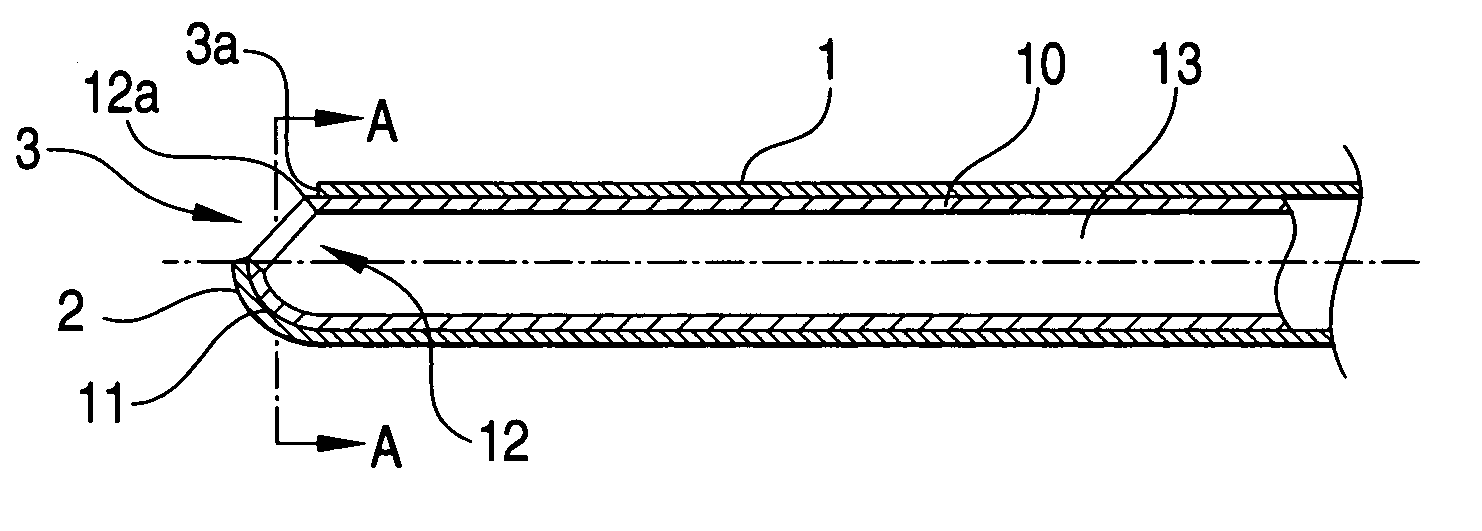
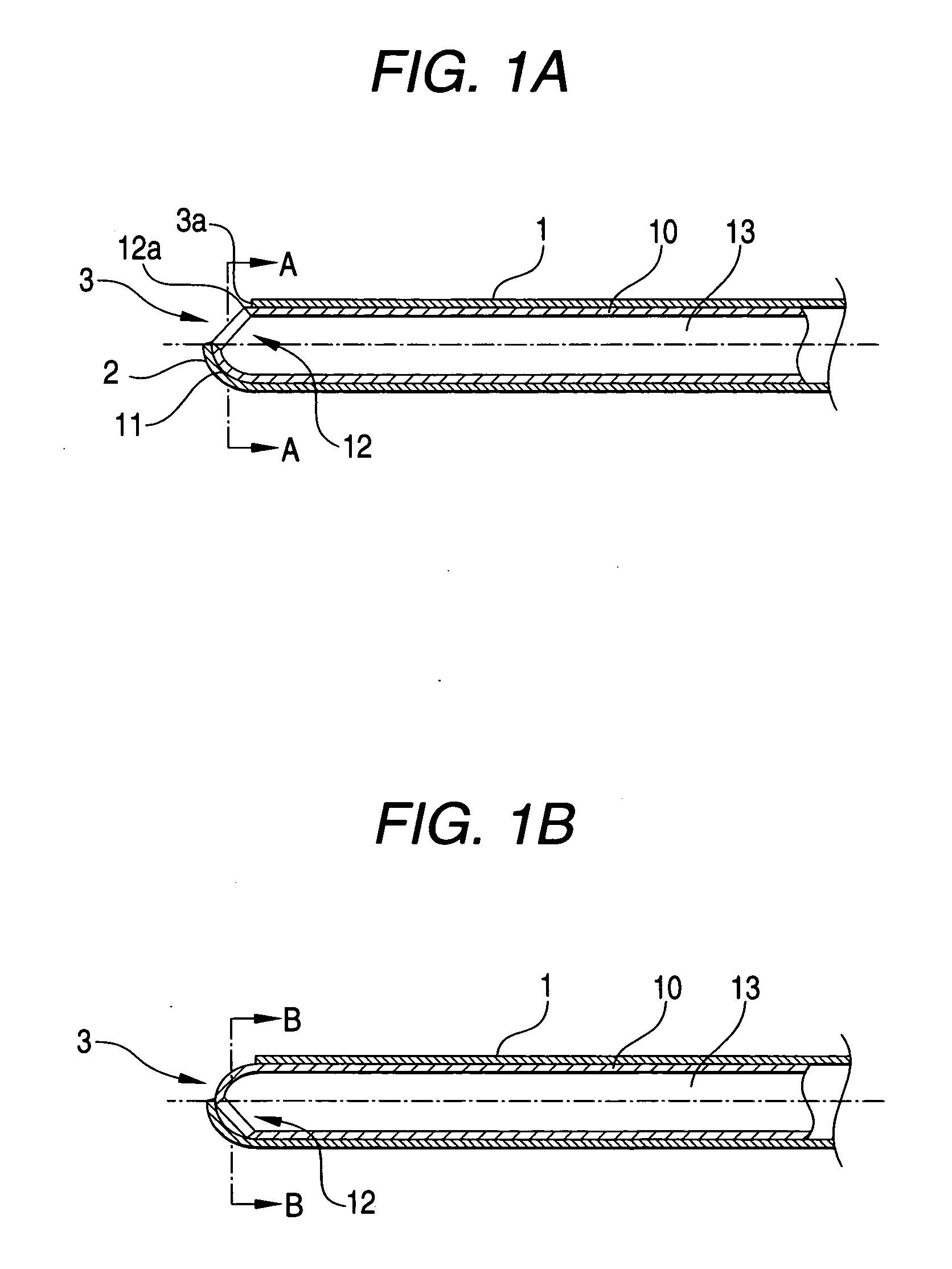
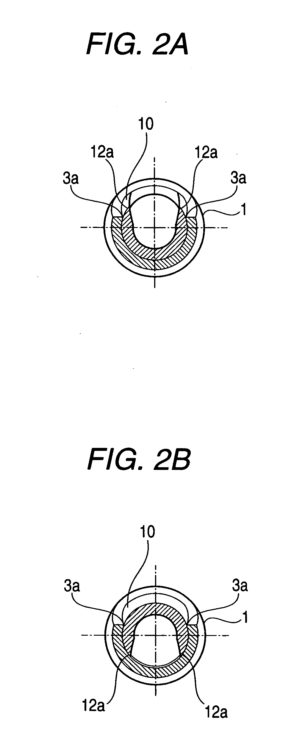
[0035] An embodiment of the invention will be explained in reference to the drawings. FIG. 3 is a schematic constitution view of a vitreous body cutter and a vitreous body surgical equipment having the same. FIGS. 1A and 1B are schematic side sectional views showing a state of fitting an inner cylindrical (tubular) blade into an outer cylindrical (tubular) blade. FIGS. 2A and 2B are schematic front sectional views showing the state of fitting the inner cylindrical blade into the outer cylindrical blade.

[0036] A vitreous body cutter 20 cuts (excises) a vitreous body V by rotating an inner cylindrical blade 10 with respect to an outer cylindrical blade 1 between a state where an opening 3 of the outer cylindrical blade 1 and an opening 12 of the inner cylindrical blade 10 overlap each other (an open state where the opening 12 can be viewed from the opening 3) (refer to FIG. 1A and FIG. 2A) and a state where the opening 3 and the opening 12 do not overlap each other (a closed state in...


PUM


Abstract

A vitreous body cutter for cutting a vitreous body in an eye includes: an inner cylindrical blade having a first suction hole and a suction path; an outer cylindrical blade having a second suction hole, the outer cylindrical blade holding the inner cylindrical blade to be rotatable about a center axis thereof; a main body fixed with the outer cylindrical blade; a diaphragm arranged in the main body, the diaphragm being linearly advanced to a distal end side of the blades in a direction of the center axis by supplying compressed gas into a gas chamber formed by the diaphragm and the main body; and a converting-and-transmitting mechanism which converts linearly advancement of the diaphragm into a rotation about the center axis and transmits the rotation to the inner cylindrical blade to rotate the inner cylindrical blade about the center axis.

Description

BACKGROUND OF THE INVENTION [0001] The present invention relates to a vitreous body cutter for cutting a vitreous body in an eye and a vitreous body surgical equipment (apparatus) having the same [0002] In a vitreous body cutter used in vitreous body surgery, a vitreous body in an eye is drawn by suction (aspiration) through a suction (aspiration) hole formed in the vicinity of an extremity (a distal end) of an outer cylindrical (tubular) blade fixed to a cutter main body, to thus cause the vitreous body to fit into the suction hole. An inner cylindrical (tubular) blade is caused to linearly reciprocate in a direction of the center axis thereof with respect to the outer cylindrical blade (a guillotine type) (refer to U.S. Pat. No. 6,383,203 (JP-A-2001-87303)) or rotationally reciprocate about the center axis (a rotary type) (refer to U.S. Pat. No. 5,176,628 (JP-A-H03-207355)), to thus excise the fitted vitreous body. [0003] Meanwhile, in the case of the guillotine type, the suction ...

Claims


Application Information

Patent Timeline
Patent Type & Authority Applications(United States)
IPC IPC(8): A61B17/14
CPCA61F9/00736
Inventor OSAWA, KOJI
Owner NIDEK CO LTD
Learn More