
Method and system for compensating thermally induced motion of probe cards

a technology of thermally induced motion and probe card, which is applied in the field of probe cards, can solve the problems of poor heat conductors and inability to eliminate them completely

Inactive Publication Date: 2006-01-05
FORMFACTOR INC
View PDF27 Cites 9 Cited by
  • Summary
  • Abstract
  • Description
  • Claims
  • Application Information

AI Technical Summary

Benefits of technology

The present invention is about a way to compensate for changes in the position of probe cards when testing integrated circuits. It includes features like energy transmissive devices, bi-material deflecting elements, and radial expansion elements. The goal is to improve the accuracy of testing.

Problems solved by technology

Insulating material such as platinum reflectors may be used to isolate the effects of the heating or cooling process to some extent, but it cannot eliminate them entirely.
Probe cards are typically built of layers of different materials and are usually poor heat conductors in a direction normal to the face of the card.

Method used


Image

  • Method and system for compensating thermally induced motion of probe cards
  • Method and system for compensating thermally induced motion of probe cards
  • Method and system for compensating thermally induced motion of probe cards

Examples


Embodiment Construction

[0062] For the purposes of promoting an understanding of the principles of the invention, reference will now be made to the embodiments illustrated in the drawings and specific language will be used to describe the same. It will nevertheless be understood that no limitation of the scope of the invention is thereby intended, and alterations and modifications in the illustrated device and method and further applications of the principles of the invention as illustrated therein, are herein contemplated as would normally occur to one skilled in the art to which the invention relates.

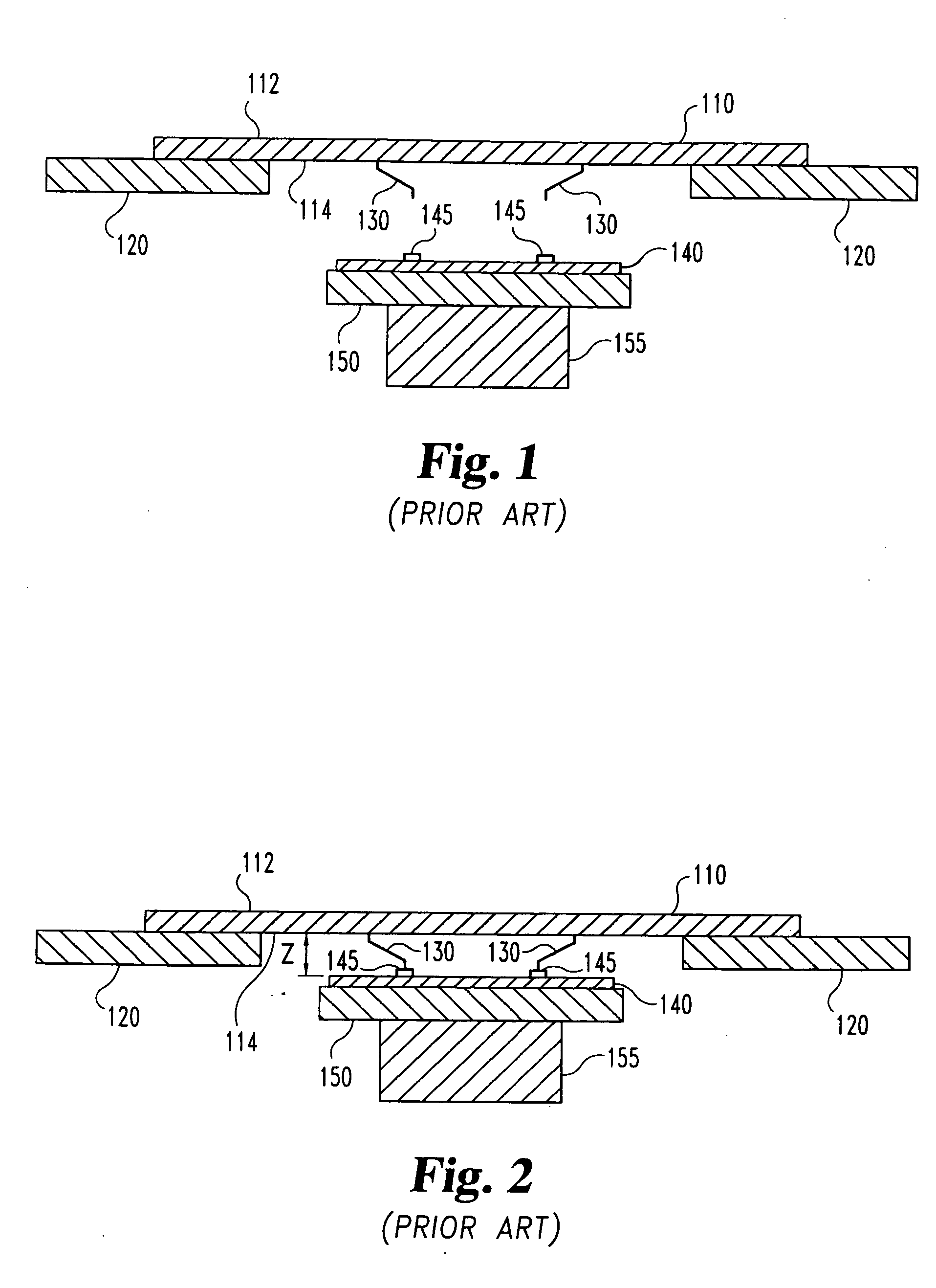
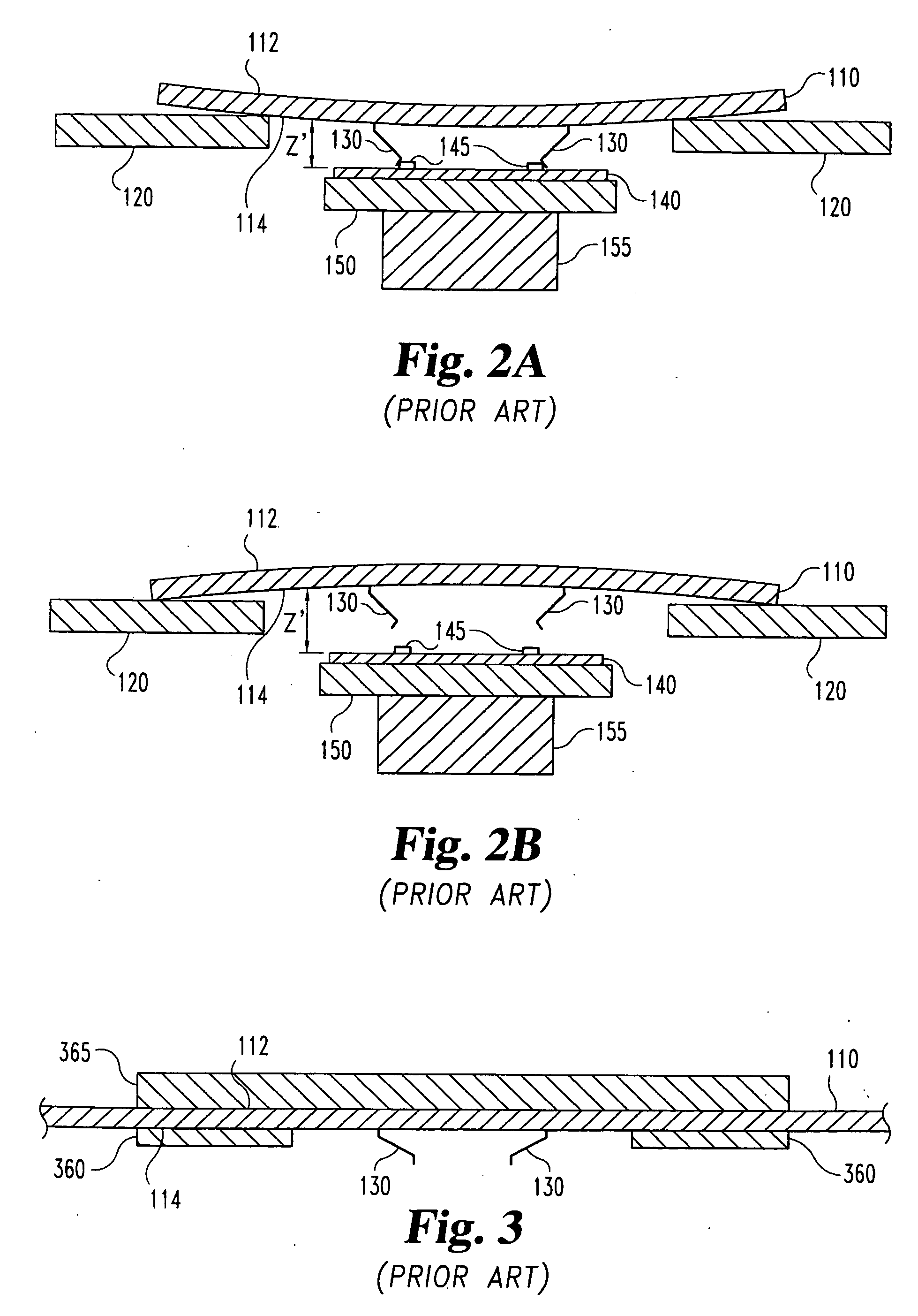
[0063]FIG. 1 shows a typical example of a probe card 110 and wafer 140 loaded into a tester. In this and the other accompanying views certain elements of certain components are shown exaggerated, for illustrative clarity. Additional components which may be mounted to the probe card, such as active and passive electronic components, connectors, and the like, are omitted for clarity. The present invention may...


PUM


Abstract

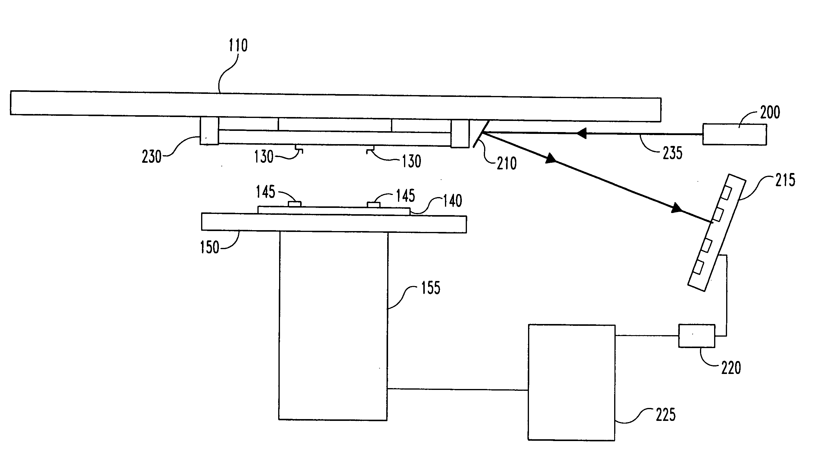
The present invention discloses a method and system compensating for thermally induced motion of probe cards used in testing die on a wafer. A probe card incorporating temperature control devices to maintain a uniform temperature throughout the thickness of the probe card is disclosed. A probe card incorporating bi-material stiffening elements which respond to changes in temperature in such a way as to counteract thermally induced motion of the probe card is disclosed including rolling elements, slots and lubrication. Various means for allowing radial expansion of a probe card to prevent thermally induced motion of the probe card are also disclosed. A method for detecting thermally induced movement of the probe card and moving the wafer to compensate is also disclosed.

Description

[0001] This application is a continuation in part of application Ser. No. 10 / 034,412 filed Dec. 27, 2001 entitled METHOD AND SYSTEM FOR COMPENSATING THERMALLY INDUCED MOTION OF PROBE CARDS which is a continuation in part of application Ser. No. 10 / 003,012 filed Nov. 2, 2001.BACKGROUND OF THE INVENTION [0002] The present invention relates to probe cards having electrical contacts for testing integrated circuits, and more specifically for a system and method to compensate for thermally induced motion of such probe cards. Probe cards are used in testing a die, e.g. integrated circuit devices, typically on wafer boards. Such probe cards are used in connection with a device known as a tester (sometimes called a prober) wherein the probe card is electronically connected to the tester device, and in turn the probe card is also in electronic contact with the integrated circuit to be tested. [0003] Typically the wafer to be tested is loaded into the tester securing it to a movable chuck. Dur...

Claims


Application Information

Patent Timeline
Patent Type & Authority Applications(United States)
IPC IPC(8): G01R31/02G01R1/067G01R1/073G01R31/28H01L21/66
CPCG01R1/07342G01R31/2891G01R31/2886
Inventor MARTENS, RODELDRIDGE, BENJAMIN N.GRUBE, GARY W.MATSUBAYASHI, KEN S.LARDER, RICHARD A.SHINDE, MAKARANDMATHIEU, GAETAN L.
Owner FORMFACTOR INC
Learn More