
Light emitting display device

a display device and light-emitting technology, applied in the direction of discharge tubes/lamp details, discharge tubes with screens, discharge tubes luminescnet screens, etc., can solve problems such as short circuits, and achieve the effects of less contact resistance, less driving voltage, and more uniform signals

Inactive Publication Date: 2006-01-05
SAMSUNG MOBILE DISPLAY CO LTD
View PDF11 Cites 4 Cited by
  • Summary
  • Abstract
  • Description
  • Claims
  • Application Information

AI Technical Summary

Benefits of technology

[0021] The present invention provides an electroluminescent device with a low contact resistance where an interconnecting line contacts a terminal, thus decreasing a driving voltage and obtaining more uniform signals.

Problems solved by technology

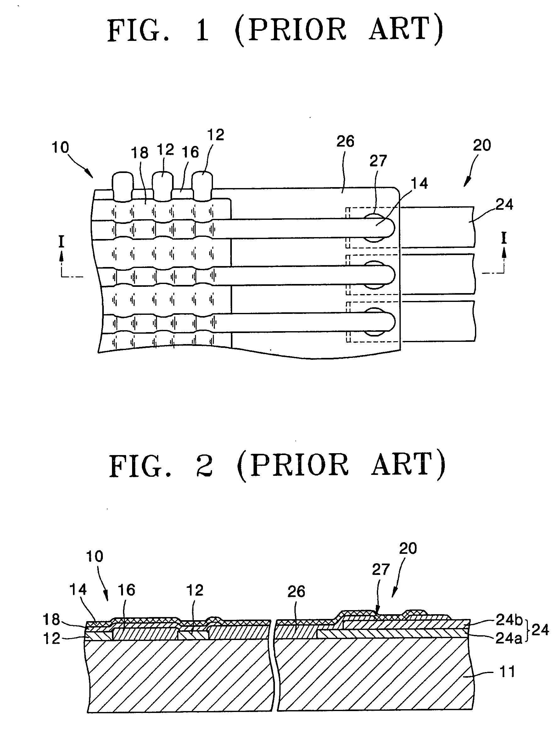
With this structure, a portion of the organic layer formed above an edge of the first electrode line can be very thin, which may cause a short circuit between the first electrode line and the second electrode line.

Method used


Image

  • Light emitting display device
  • Light emitting display device
  • Light emitting display device

Examples


Embodiment Construction

[0038] The present invention will now be described more fully with reference to the accompanying drawings showing exemplary embodiments of the present invention. Exemplary embodiments of the present invention relate to organic light emitting display devices including an organic emission layer. However, techniques according to the present invention can also be used to form inorganic light emitting display devices including an inorganic emission layer.

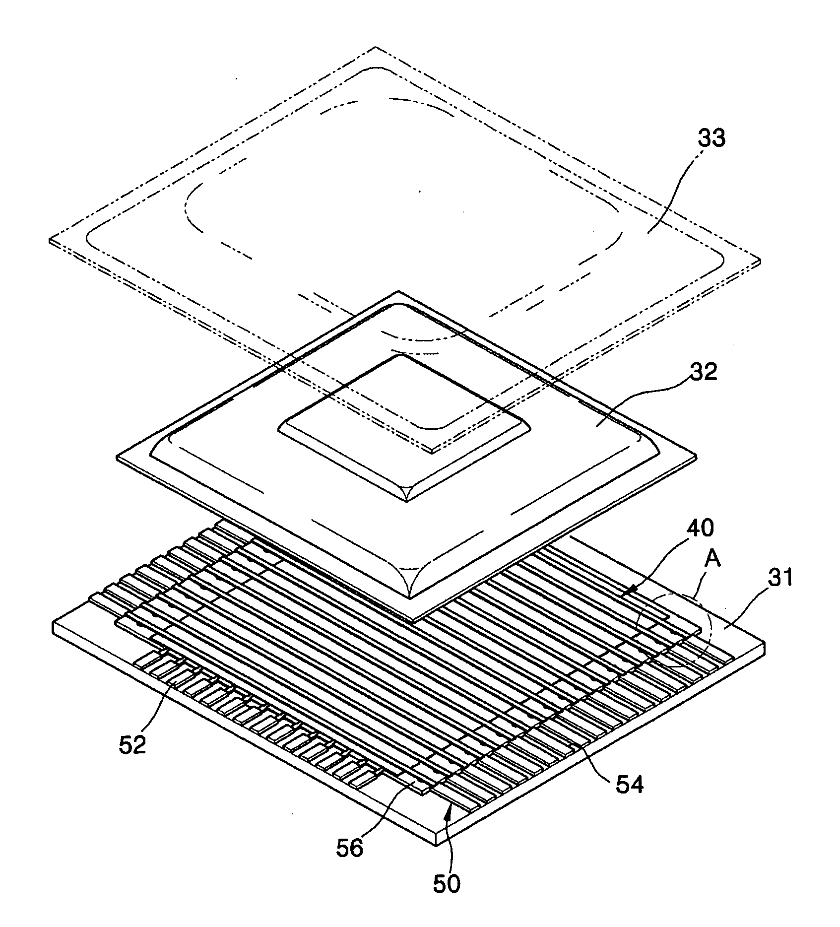
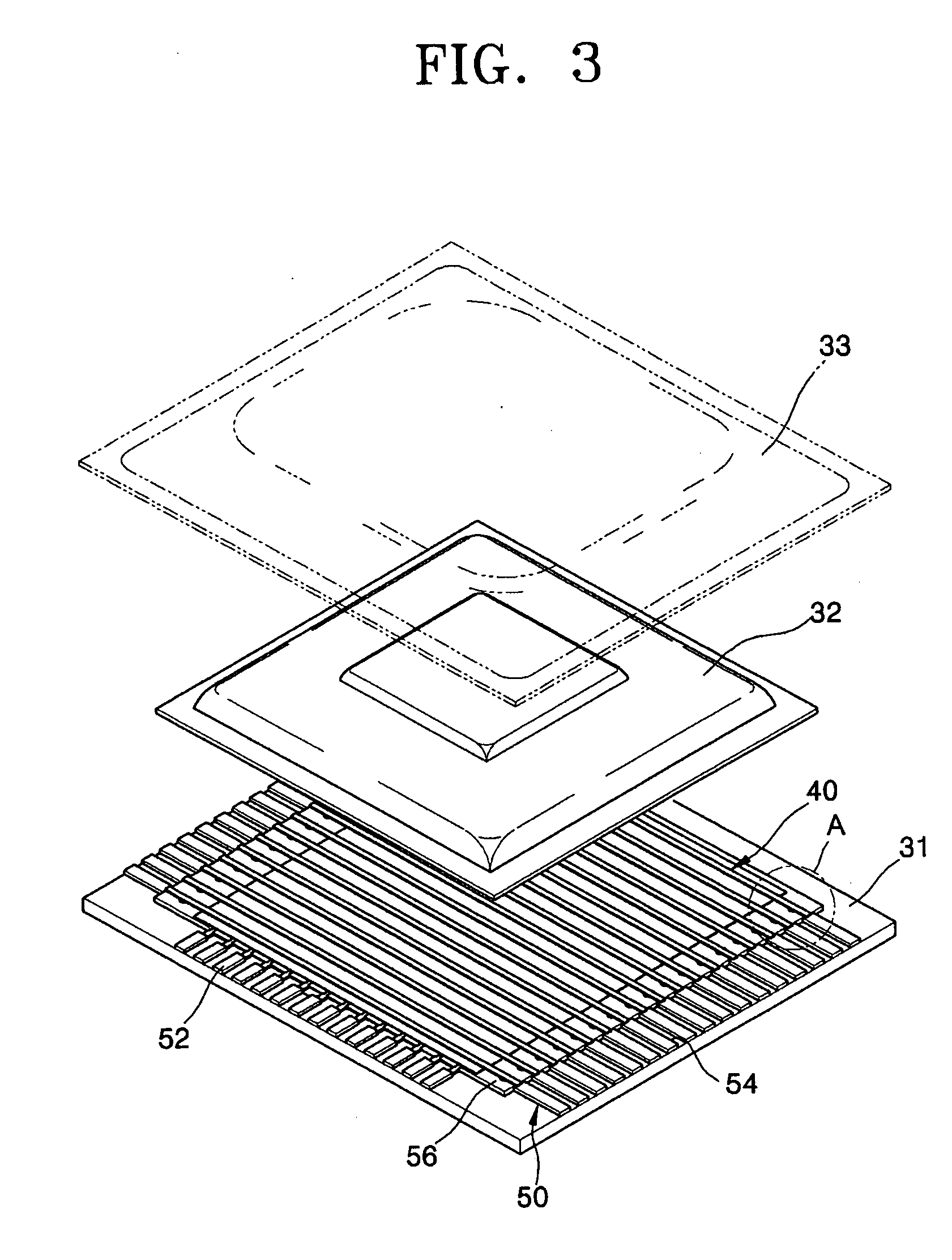
[0039]FIG. 3 is an exploded perspective view showing an organic light emitting display device according to an exemplary embodiment of the present invention.

[0040] Referring to FIG. 3, the organic light emitting display device according to an exemplary embodiment of the present invention may include a substrate 31, an emission unit 40, which forms an image and may be disposed on an upper surface of the substrate 31, a sealing element 32, which seals the emission unit 40 with the substrate 31, and terminals 50 applying a current to the e...


PUM


Abstract

A light emitting display device including a substrate, an emission unit that forms an image and is disposed on the substrate, a plurality of terminals contacting a plurality of interconnecting lines electrically connected to the emission unit, and a contact resistance controlling portion which decreases a contact resistance between a terminal and an interconnecting line and is disposed where the terminal contacts the interconnecting line.

Description

CROSS-REFERENCE TO RELATED PATENT APPLICATION [0001] This application claims priority to and the benefit of Korean Patent Application No. 10-2004-0051524, filed on Jul. 2, 2004, which is hereby incorporated by reference for all purposes as if fully set forth herein. BACKGROUND OF THE INVENTION [0002] 1. Field of the Invention [0003] The present invention relates to a light emitting display device, and more particularly, to a light emitting display device having decreased contact resistance between an interconnecting line and a terminal. [0004] 2. Discussion of the Background [0005] Generally, self-emissive light emitting display devices have many advantages. For example, they may have wide viewing angles, excellent contrast, and high response speed. Due to these advantages, self-emissive light emitting display devices are regarded as next generation display devices. Light emitting display devices may be inorganic or organic devices depending upon the material comprising their emissi...

Claims


Application Information

Patent Timeline
Patent Type & Authority Applications(United States)
IPC IPC(8): H05B33/00H05B44/00
CPCH01L27/3288H01L27/156H10K59/179H05B33/06
Inventor CHAE, BYUNG-HOONKIM, SEON-HEENAM, WI-JIN
Owner SAMSUNG MOBILE DISPLAY CO LTD
Learn More