
Acoustic fluid machine

a technology of acoustic fluid and acoustic resonator, which is applied in the direction of mechanical equipment, machines/engines, functional valve types, etc., can solve the problems of high production and installation costs, and achieve the effect of reducing the length of the acoustic resonator and high intake/discharge

Active Publication Date: 2006-01-05
REACTIVE SURFACES +1
View PDF10 Cites 2 Cited by
  • Summary
  • Abstract
  • Description
  • Claims
  • Application Information

AI Technical Summary

Benefits of technology

[0008] In view of the disadvantages, it is therefore an object of the present invention to provide an acoustic fluid machine in which the length of the acoustic resonator relative to the diameter of the piston is minimized, thereby achieving an increase in its applicability and a reduction in the production cost.
[0010] In accordance with the present invention, even if the piston has a very large diameter, since sound waves generated on the surface of the piston by vibration are concentrated effectively on the intake / discharge valve device at the upper end of the acoustic resonator, a high intake / discharge effect can be attained, and consequently it is possible to decrease the length of the acoustic resonator relative to the diameter of the piston.

Problems solved by technology

However, for a given intended performance, if the length of the acoustic resonator is too large, its application is restricted, and the cost of production and installation becomes high.

Method used


Image

  • Acoustic fluid machine
  • Acoustic fluid machine
  • Acoustic fluid machine

Examples


Embodiment Construction

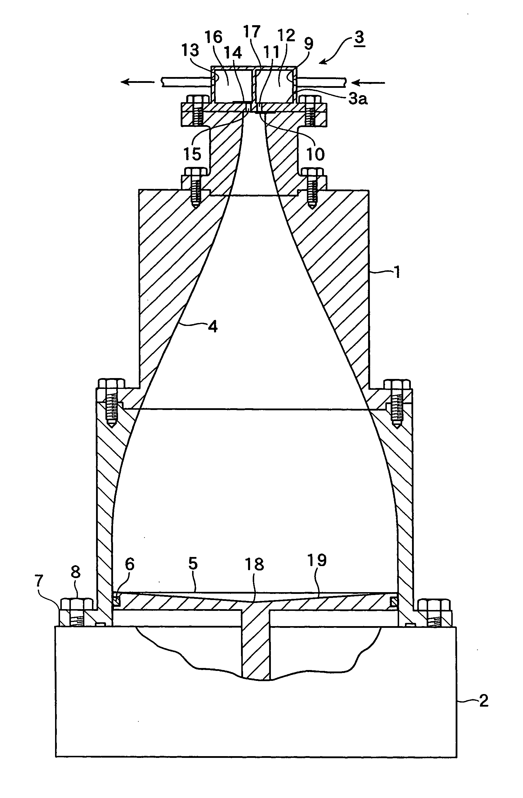
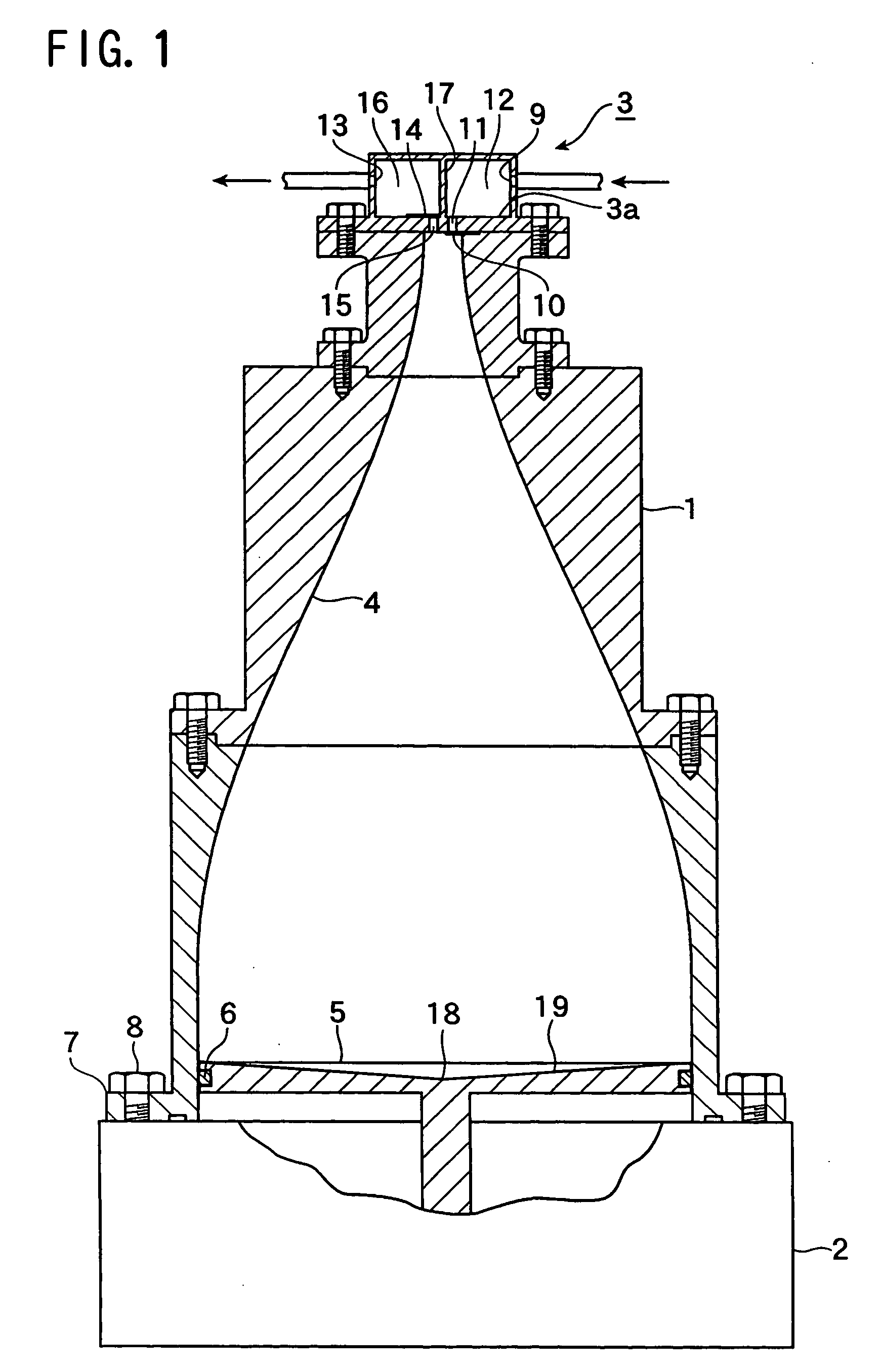
[0014] An acoustic fluid machine is formed by mounting an actuator 2 under the larger-diameter lower end at the base of an acoustic resonator 1, and a valve device 3 on the smaller-diameter upper end of the acoustic resonator 1.

[0015] The acoustic resonator 1 has a resonant cavity 4 having the larger-diameter lower end, and the diameter gradually decreases toward the top. The dimensions of the resonant cavity 4 are such that, for example, when the length from the lower end to the upper end is approximately 100, the diameter of the upper end is approximately 5 and the diameter of the lower end is approximately 35.

[0016] The actuator 2 functions also as a support platform, and reciprocates a piston 5 connected to the actuator 2. The piston 5 is made of light alloy and is fitted in the lower end of the resonant cavity 4, the outer periphery of the piston 5 being equipped with a seal 6.

[0017] An outer portion 19 of the surface of the piston 5 is inclined gradually upward from the cen...


PUM


Abstract

An acoustic fluid machine includes an acoustic resonator, a valve device, a piston, and an actuator. The acoustic resonator has a larger-diameter base and a smaller-diameter upper end. The valve device is provided on the upper end of the acoustic resonator and has a sucking hole and a discharge hole. The piston is provided in the base of the acoustic resonator and has a surface such that the distance between the upper end of the acoustic resonator and the upper surface of the piston is substantially constant over the whole surface of the piston. The actuator is connected to the piston and reciprocates the piston at high speed axially with a very small amplitude so that a gas is sucked into the acoustic resonator via the sucking hole and discharged via the discharge hole by virtue of pressure fluctuations within the acoustic resonator.

Description

BACKGROUND OF THE INVENTION [0001] The present invention relates to an acoustic fluid machine for a gas, the machine utilizing acoustic resonance-based fluctuations in pressure amplitude. [0002] There is a known acoustic fluid machine in which a piston is reciprocated by an actuator at high speed axially with a very small amplitude is provided in a larger-diameter base of an acoustic resonator, and a gas is sucked into the acoustic resonator and discharged therefrom via the smaller-diameter upper end by virtue of pressure fluctuations within the acoustic resonator accompanying the reciprocation of the piston. [0003] This acoustic fluid machine utilizes fluctuations in the pressure amplitude of standing acoustic waves generated by resonance of a gas column inside the tube accompanying movement of the piston when the piston reciprocates axially with a very small amplitude, and comprises as an operating part only an actuator that causes the piston in the base of the acoustic resonator ...

Claims


Application Information

Patent Timeline
IPC IPC(8): F01N1/14F01N1/00F16K17/00
CPCF04F7/00
Inventor KAWAHASHI, MASAAKIFUJIOKA, TAMOTSUSAITO, MASAYUKI
Owner REACTIVE SURFACES
Learn More