
Dual-durometer divided bar

a technology of divided bars and durometers, applied in the field of prefabricated construction elements, can solve the problems of detracting from the aesthetic appearance of decorative divider bars, painting or tinted surfaces exposed to air, and the conventional divider bars are quite functional in appearance, and achieve good sealing

Inactive Publication Date: 2006-01-05
CRANE COMPOSITES
View PDF5 Cites 14 Cited by
  • Summary
  • Abstract
  • Description
  • Claims
  • Application Information

AI Technical Summary

Benefits of technology

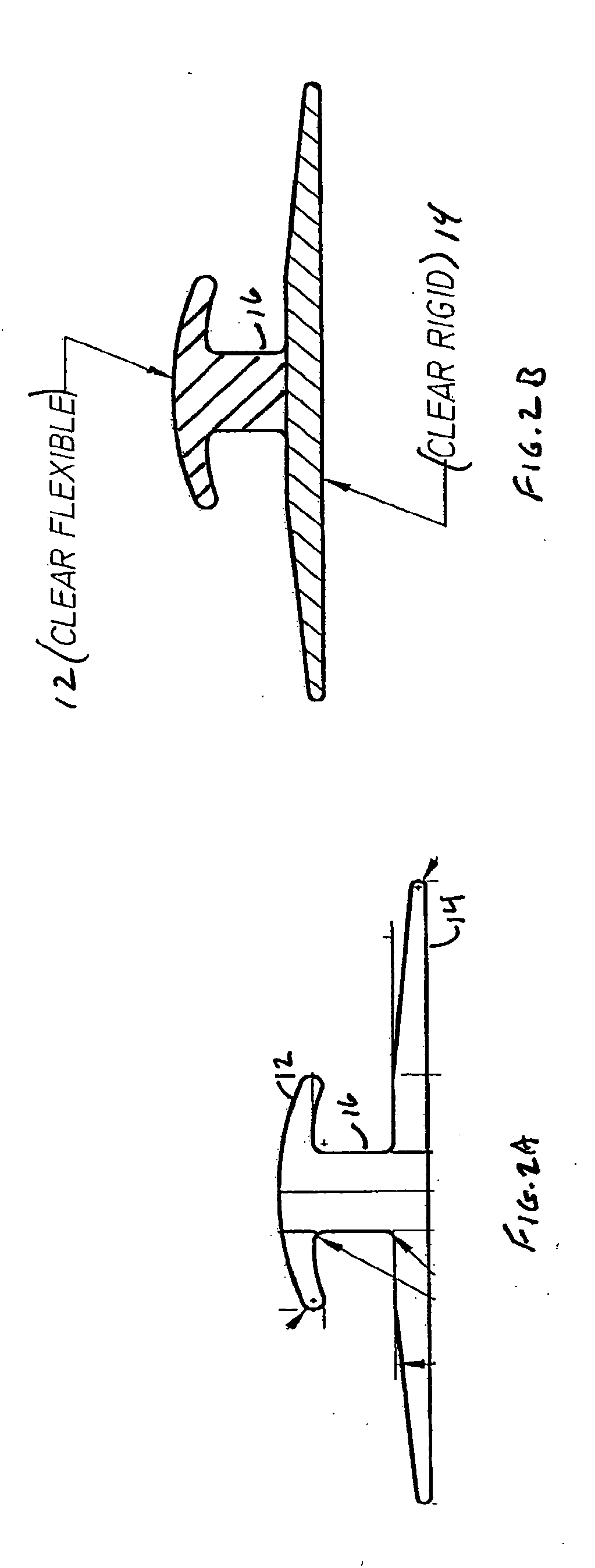
[0011] One aspect of the invention is a divider bar for use with paneling, which comprises a first and a second portion and a stem portion joining the first and second portions. The first and second portions are shaped and arranged to engage an edge region of at least one panel, and the first portion is made of a first material, and the second portion is made of a second material. Preferably, the first material is relatively flexible, while the second material is relatively rigid. In particular, the flexibility of the first material should be such that when the edge of the panel is engaged by the divider bar, the result is a good seal between the panel and the bar even without the use of a caulk or sealant, and this seal is maintained even if the panel expands or contracts (for example, under the influence of temperature). The first and second materials are also preferably transparent, or at least the first is. A colorant may be added to the second material, or a decorative material may be applied underneath the transparent portion, so as to be visible through the transparent portion.

Problems solved by technology

A conventional divider bar is quite functional in appearance, however, and may detract from the esthetic appearance of such a decorative panel, the exposed surface of which may bear a decorative pattern.
Painting or similarly tinting a conventional division molding, however, has the disadvantage that the painted or tinted surface is exposed to the air.

Method used


Image

  • Dual-durometer divided bar
  • Dual-durometer divided bar
  • Dual-durometer divided bar

Examples


Embodiment Construction

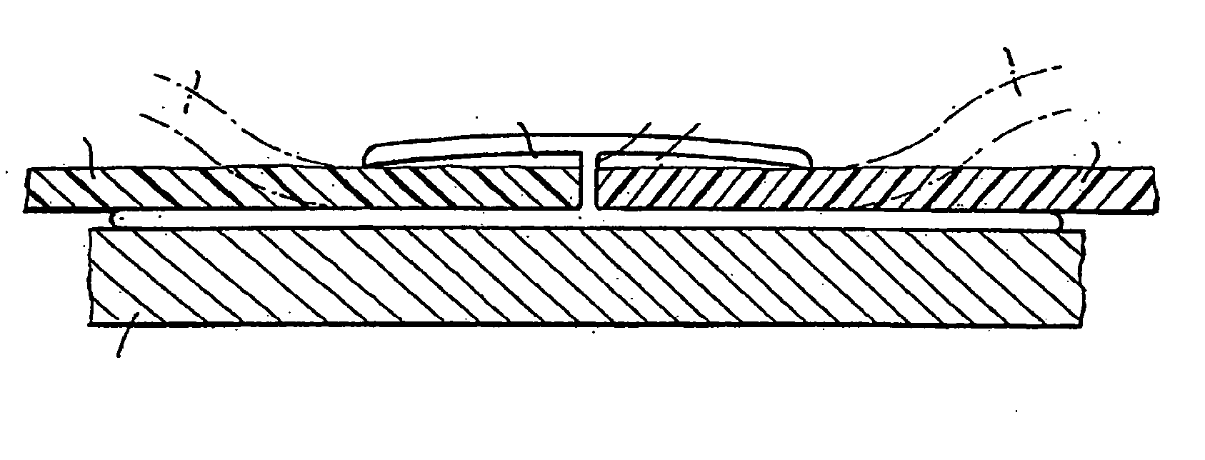
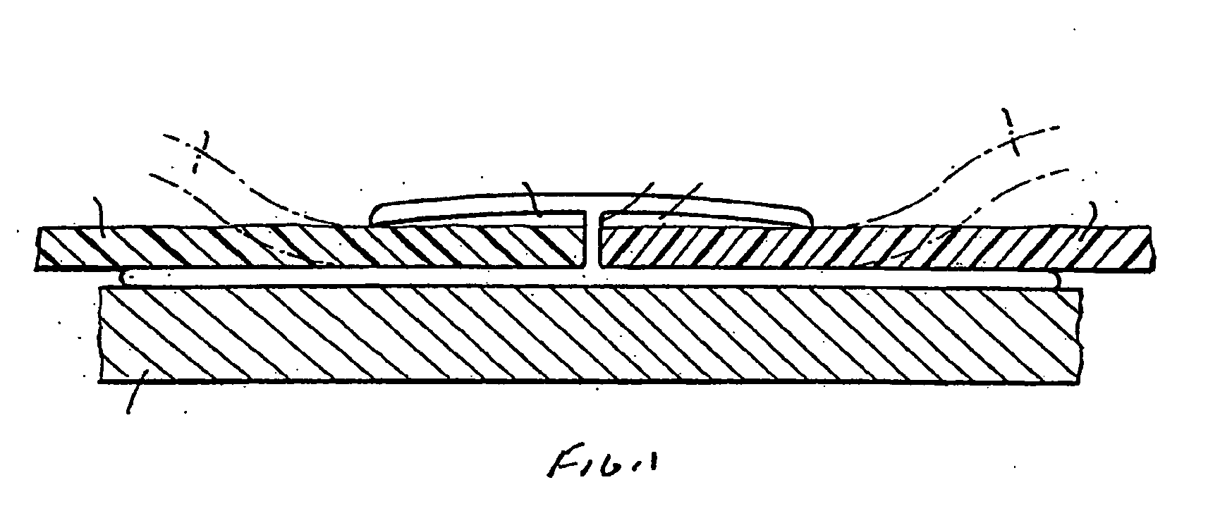
[0018] As is well known, divider bars are conventionally used to provide a seal between adjacent FRP panels. Part of the divider bar extends from the backing surface, and has two channels formed in it, to receive the edges of two panels. Conventionally, adhesive or caulk is laid down in the channels, or on the edge of the panels, and the panel edges are then placed in the channel portions of the divider bars. A portion of the divider bar remains visible after installation. As will be appreciated from the following, the preferred embodiment of the present invention is a divider bar that can be used with no need for any caulk or sealant. An example is shown in FIG. 1, illustrating the engagement of the divider bar with two sheets of paneling (all shown in section).

[0019] According to the preferred embodiment of the present invention, the divider bar has a first portion 12, which remains visible after installation, and a second portion 14 that floats behind the panels. The first and s...


PUM


Abstract

A divider bar for use with paneling, has a first and a second portion and a stem portion joining the first and second portions. The first and second portions are shaped and arranged to engage an edge region of at least one panel, and are made of a first and a second material, respectively. The first material is preferably more flexible than that of the second portion, and is such as to provide a good seal with a panel engaged by the divider bar. This characteristic of the divider bar can provide an expansion / contraction joint that maintains the seal even if the panel expands or contracts (e.g., due to temperature changes). Preferably, both materials are transparent and at least the first is colorless, the second in that case optionally having a coloring, or a decorative material being applied to the second portion of the divider bar to be visible through the transparent first portion. It is preferred that the product be made by extrusion, and especially by a co-extrusion process.

Description

BACKGROUND OF THE INVENTION [0001] 1. Field of the Invention [0002] The present invention relates generally to the field of prefabricated construction elements such as construction panels and other elements to be used therewith, and relates more particularly to divider bars used with such panels. [0003] 2. Related Background Art [0004] The use of pre-made panels in the construction of interior walls, ceilings, etc., is well known. Many such panels are commercially available, from a great variety of materials. Fiberglass-reinforced plastic (“FRP”) panels have been used for this purpose, and examples of recent developments relating to such panels are disclosed in commonly assigned co-pending applications Nos. 10 / 081,629 and 10 / 360,785, the contents of both of which are incorporated herein by reference. [0005] Fiberglass-reinforced plastic panels are widely used throughout the construction and building materials industry. That material offers a number of significant and advantageous fe...

Claims


Application Information

Patent Timeline
IPC IPC(8): E04C3/00
CPCE04F19/065E04F19/062
Inventor TAYLOR, STEVEN J.
Owner CRANE COMPOSITES
Learn More