
Matrix pattern match techniques for uninstalling multiple dependent components

a matrix pattern and component technology, applied in the field of managing software components, can solve the problems of only working recursive algorithms, tedious and difficult programs, and typical mechanisms used to identify components, and achieve the effect of safe uninstallation and rapid determination

Inactive Publication Date: 2005-12-29
IBM CORP
View PDF11 Cites 39 Cited by
  • Summary
  • Abstract
  • Description
  • Claims
  • Application Information

AI Technical Summary

Benefits of technology

[0015] Conveniently, software exemplary of an embodiment of the present invention may allow use of a matrix pattern match technique to resolve uninstall problems for multiple dependent components typically in a more expedient manner than before.

Problems solved by technology

In the art of software component maintenance, components may typically be installed and uninstalled many times during the useful life cycle of the components.
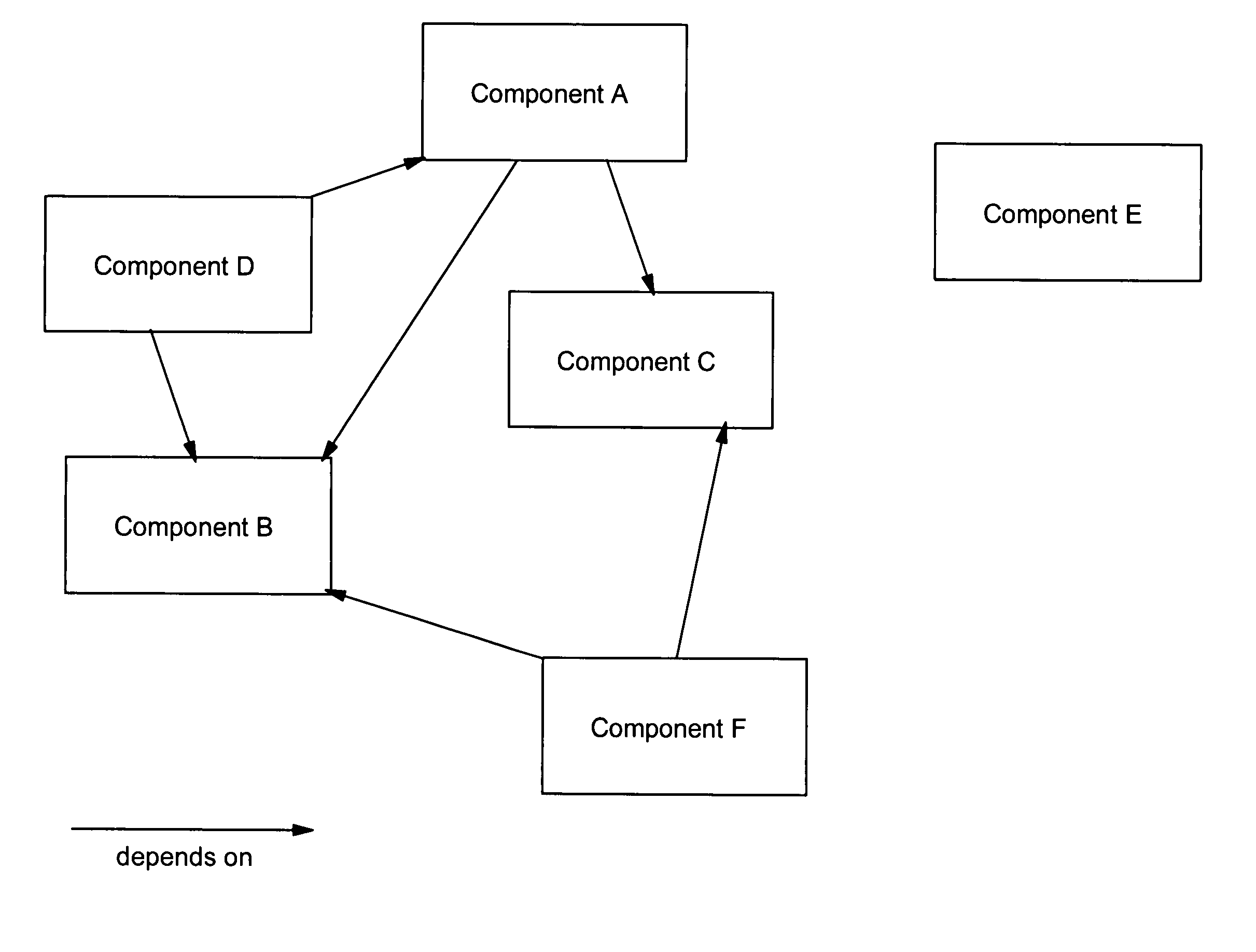
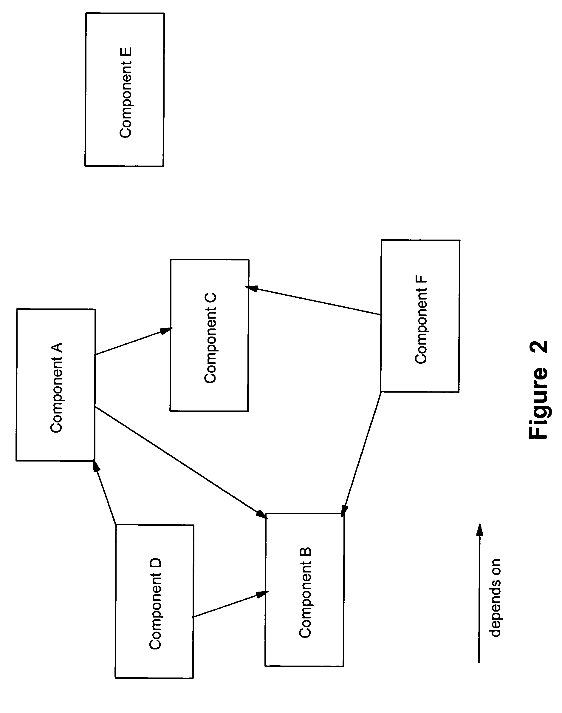
Typically there is a programming issue regarding the uninstall of multiple components in which the components may have a nested dependency with one another.
Typical mechanisms used to identify components that have no other components depending there from are tedious and difficult to program.
However, the recursive algorithm may only work if all components are connected to describe a dependency among them.
Using a recursive routine plus a for-loop to resolve the simple type of problem stated in the example may prove to be slow and difficult to program.

Method used


Image

  • Matrix pattern match techniques for uninstalling multiple dependent components
  • Matrix pattern match techniques for uninstalling multiple dependent components
  • Matrix pattern match techniques for uninstalling multiple dependent components

Examples


Embodiment Construction

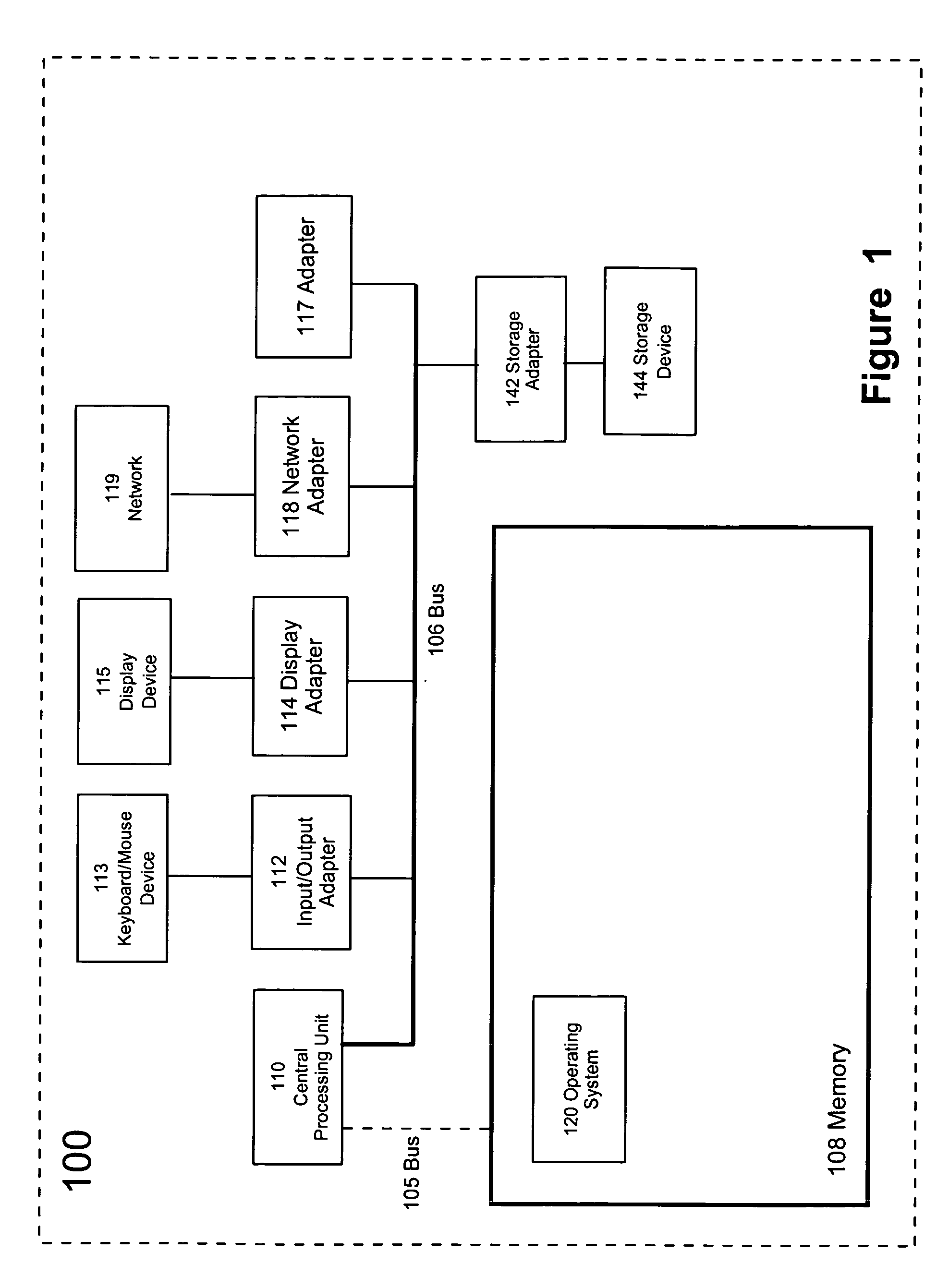
[0029]FIG. 1 depicts, in a simplified block diagram, a computer system 100 suitable for implementing embodiments of the present invention. Computer system 100 has a central processing unit (CPU) 110, which is a programmable processor for executing programmed instructions 126 stored in memory 108. Memory 108 can also include hard disk, tape or other storage media. While a single CPU is depicted in FIG. 1, it is understood that other forms of computer systems can be used to implement the invention, including multiple CPUs. It is also appreciated that the present invention can be implemented in a distributed computing environment having a plurality of computers communicating via a suitable network 119, such as the Internet.

[0030] CPU 110 is connected to memory 108 either through a dedicated system bus 105 and / or a general system bus 106. Memory 108 can be a random access semiconductor memory for storing components of an embodiment of the present invention such as matrices or tables as...


PUM


Abstract

There is disclosed a data processing system-implemented method, system and an article of manufacture for tracking software component dependencies among a set of multiple dependent software components of an application. In one aspect there is means for creating an n-dimensional matrix of predefined size in which is established a first dimension to represent the software components and a second dimension to represent the cross component dependencies. Next there is placed in each cell a value indicating an absence or a presence of a software component dependency within the set of multiple dependent software components of the application to create a software component dependency matrix. In a second aspect for uninstalling multiple dependent software components for a selected application from a computer system one then obtains the software component dependency matrix for the selected application. Next there is determined a candidate software component from the software component dependency matrix for removal. Next follows the process of uninstalling the candidate software component from the computer system and updating the software component dependency matrix to reflect removal of the candidate software component. The process of determining, uninstalling, and updating is repeated until all multiple dependent software components for the selected application have been uninstalled from the computer system.

Description

FIELD OF THE INVENTION [0001] This present invention relates generally to managing software components and more particularly to uninstalling multiple dependent software components. BACKGROUND OF THE INVENTION [0002] In the art of software component maintenance, components may typically be installed and uninstalled many times during the useful life cycle of the components. Typically there is a programming issue regarding the uninstall of multiple components in which the components may have a nested dependency with one another. When multiple components are uninstalled, the existing dependencies for the different components may prevent users from uninstalling those components due to their dependencies. For example, if a component is one component on which one or more other components depends, then that component cannot be uninstalled first since other components depend on it. In order to uninstall all components, users must first uninstall components which do not have any components de...

Claims


Application Information

Patent Timeline
IPC IPC(8): G06F9/44G06F9/445
CPCG06F8/62
Inventor CHEN, PAUL MINGVYTAS, PAUL DARIUS
Owner IBM CORP
Learn More