
Battery module

a battery module and module technology, applied in the field of batteries, can solve the problem of not meeting the capacity and power requirements of the battery modul

Inactive Publication Date: 2005-12-29
SAMSUNG SDI CO LTD
View PDF3 Cites 47 Cited by
  • Summary
  • Abstract
  • Description
  • Claims
  • Application Information

AI Technical Summary

Benefits of technology

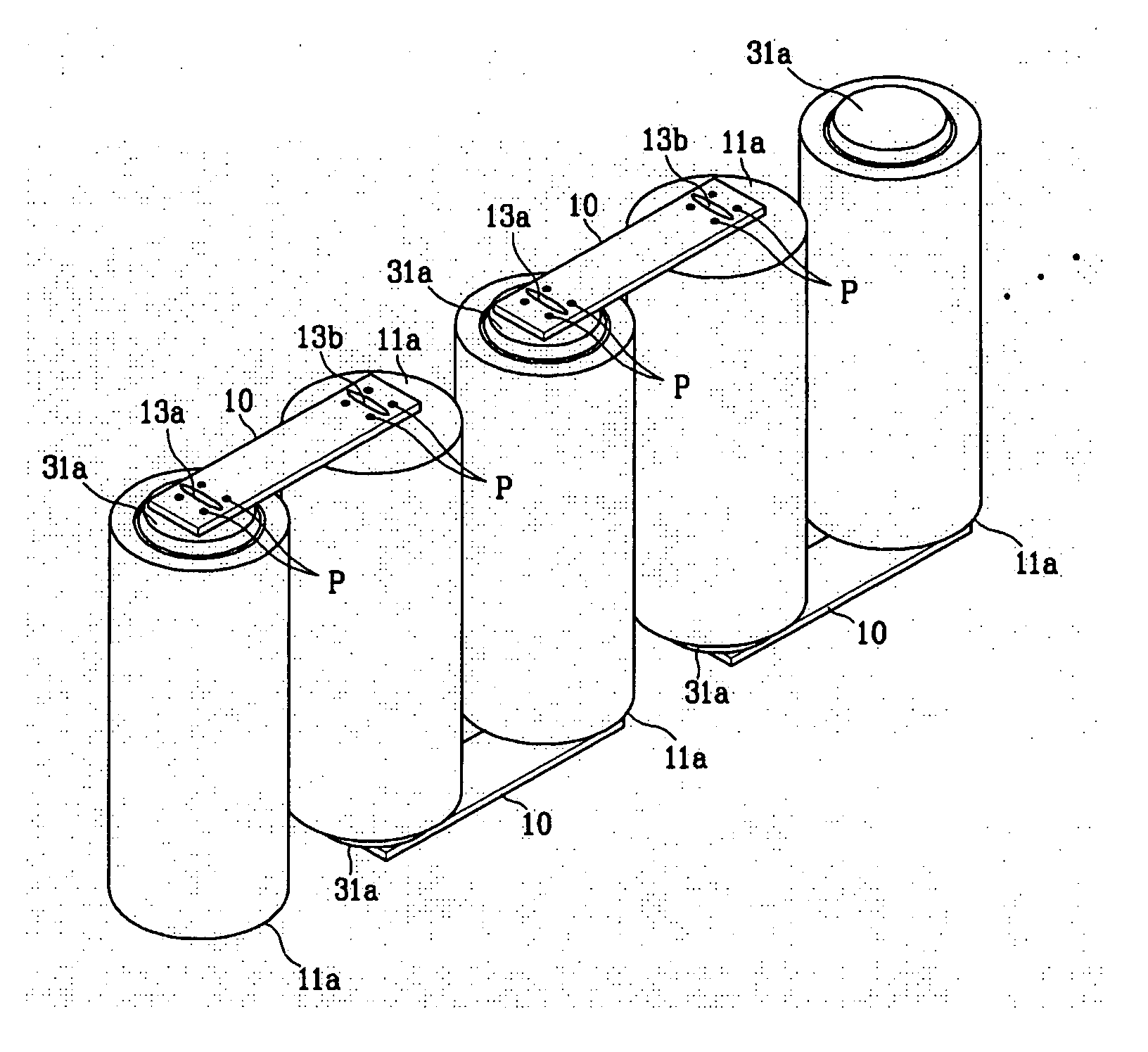
[0014] The present invention provides a battery module in which coupling between the battery cells is more secure.

Problems solved by technology

When a rechargeable battery is applied to a battery module by itself, it cannot satisfy the capacity and power requirements for the battery module.
Particularly, these problems are often caused in resistance welding where the contacting area is melted using a large current.

Method used


Image

  • Battery module
  • Battery module
  • Battery module

Examples


Embodiment Construction

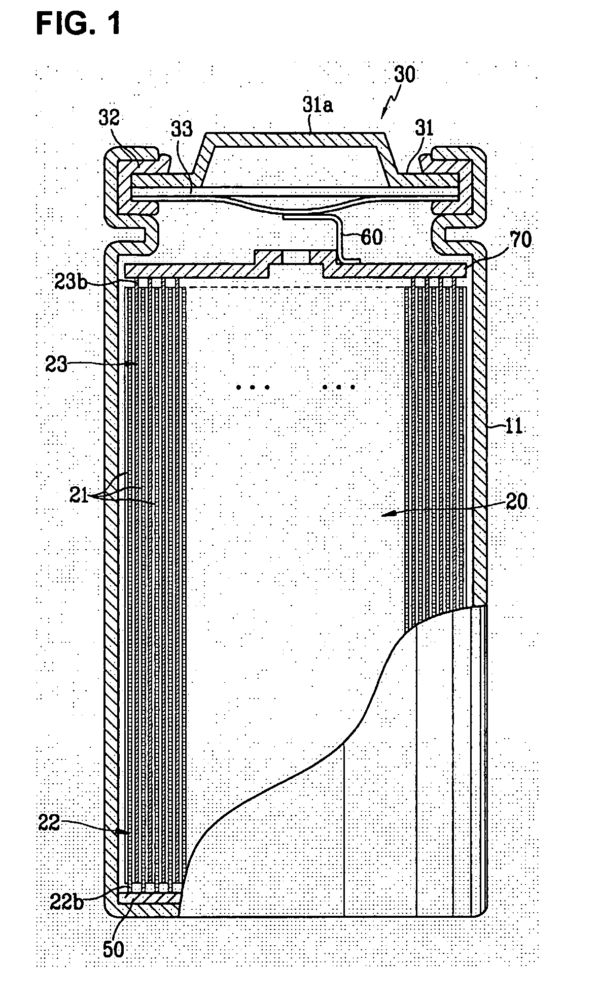
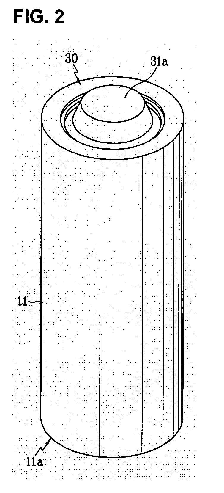
[0025] The present invention relates to a battery module that includes a plurality of battery cells that are coupled with each other to provide a pack system. The battery module of the present invention can decrease the contact resistance and fix the cells together more securely. Thus, the battery module of the present invention improves the operating characteristics by increasing the coefficient for collecting the current.

[0026] In the battery module of the present invention, terminals of a positive electrode and a negative electrode of the battery cells are coupled together with a connection member that includes holes. The holes may be present at both ends and are formed through the connection member to prevent transmission of electric current. Preferably, the hole is a cutout hole that is capable of completely interrupting the current. More preferably, the hole may be formed into a slot. In addition, the hole includes an insulating material.

[0027] The terminals are coupled with...


PUM

PropertyMeasurementUnit
total lengthaaaaaaaaaa
lengthaaaaaaaaaa
shapeaaaaaaaaaa

Abstract

A battery module including a plurality of battery cells, wherein the terminal of a positive electrode and the terminal of a negative electrode of the battery cells are coupled through a connection member that includes holes is disclosed.

Description

CROSS REFERENCE TO RELATED APPLICATION [0001] This application claims priority to and the benefit of Korean Patent Application No. 10-2004-0047017 filed on Jun. 23, 2004, which is hereby incorporated by reference for all purpose as if fully set forth herein. BACKGROUND OF THE INVENTION [0002] 1. Field of the Invention [0003] The present invention relates to a battery module with an improved connecting structure between high power rechargeable batteries. [0004] 2. Description of the Related Art [0005] Generally, a rechargeable battery is classified into a low capacity rechargeable battery or a “battery cell” in which one or several rechargeable unit cells are packaged into a pack shape, or a high capacity rechargeable battery or a “battery module” in which several tens of battery cells are assembled depending upon the desired usage and battery capacity. Battery cells are mainly used as power sources for various portable electronic devices such as cellular phones, laptop computers, an...

Claims


Application Information

Patent Timeline
Patent Type & Authority Applications(United States)
IPC IPC(8): H01M50/505H01M50/51H01M50/516H01M50/528H01M50/529
CPCH01M2/204Y02E60/10H01M50/516H01M50/51H01M50/505H01M50/50H01M50/528
Inventor KIM, JAE-KYUNGCHEON, SANG-EUNYOO, SEOK-YOONYOON, HYE-WON
Owner SAMSUNG SDI CO LTD
Learn More