
Optical apparatus

a technology of optical apparatus and asymmetrical beam, which is applied in the field of optical apparatus, can solve the problems of increasing the cost of shutter units, increasing the size of shutter units, and asymmetrical off-axis beams, so as to prevent light quantity and uniform brightness, reduce the thickness of the entire image-taking apparatus, and reduce the effect of thickness

Inactive Publication Date: 2005-12-29
KONICA MINOLTA PHOTO IMAGING
View PDF5 Cites 15 Cited by
  • Summary
  • Abstract
  • Description
  • Claims
  • Application Information

AI Technical Summary

Benefits of technology

"The present invention provides an image-taking apparatus that can reduce the thickness of the apparatus and achieve uniform brightness even when using an inexpensive and small-size shutter unit. This is achieved by providing a lens system with a movable lens unit that changes the focal length of the lens system, a shutter disposed on the object side of the most image-side lens unit, and an aperture stop for determining the f-number. The shutter moves in a way that ensures the off-axial beam is uniformly cut, preventing any difference in light quantity between both ends of the formed image. This results in a thinner image-taking apparatus and a formed image with uniform brightness, even when using an inexpensive and small-size shutter unit. The use of this image-taking apparatus for appliances such as digital cameras and personal digital assistants contributes to smaller size, higher performance, and lower cost of these apparatuses."

Problems solved by technology

A shutter unit is frequently disposed in the vicinity of the aperture stop that determines the f-number, and cutting, by the shutter, the off-axial beam that is asymmetrical with respect to the optical axis is a problem.
However, a driver for moving a plurality of shutter blades is required and this increases the cost of the shutter unit.
In addition, since it is necessary to secure a space for a plurality of shutter blades to retract into, the shutter unit is increased in size, so that it is difficult to reduce the thickness of the entire image-taking apparatus.

Method used


Image

  • Optical apparatus
  • Optical apparatus
  • Optical apparatus

Examples


examples

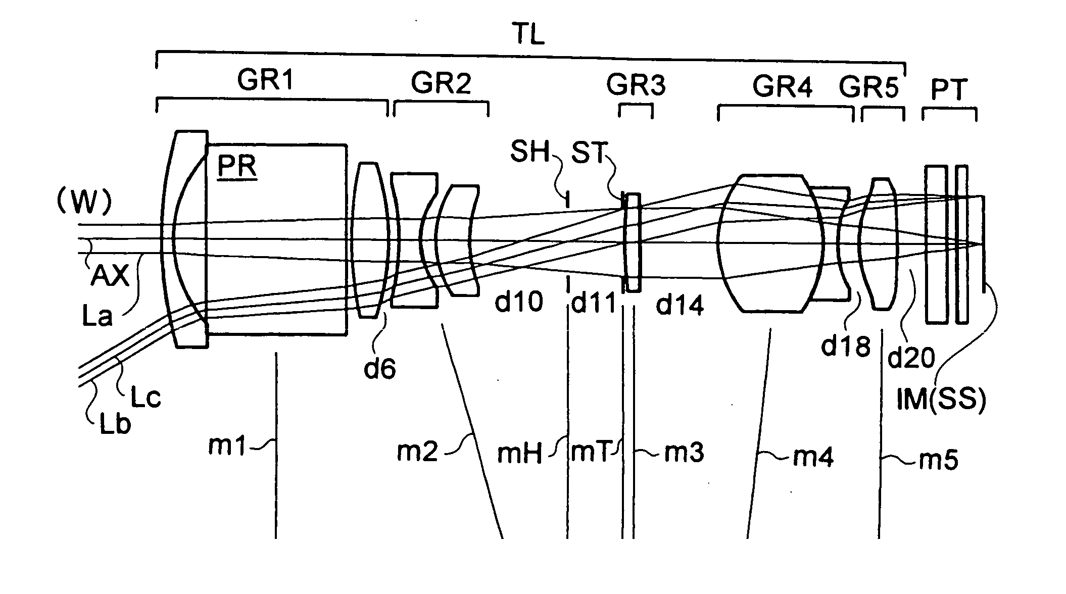
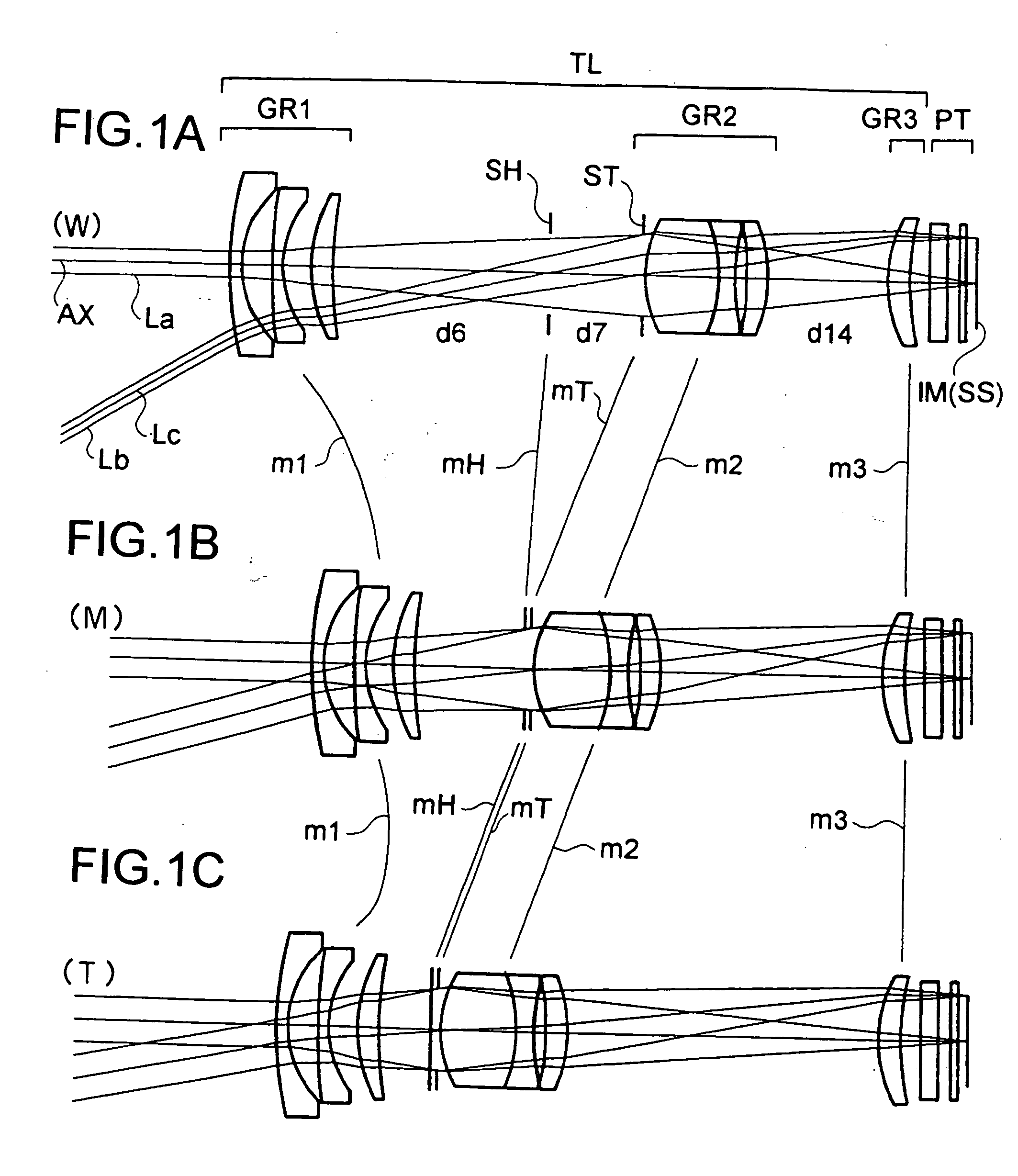
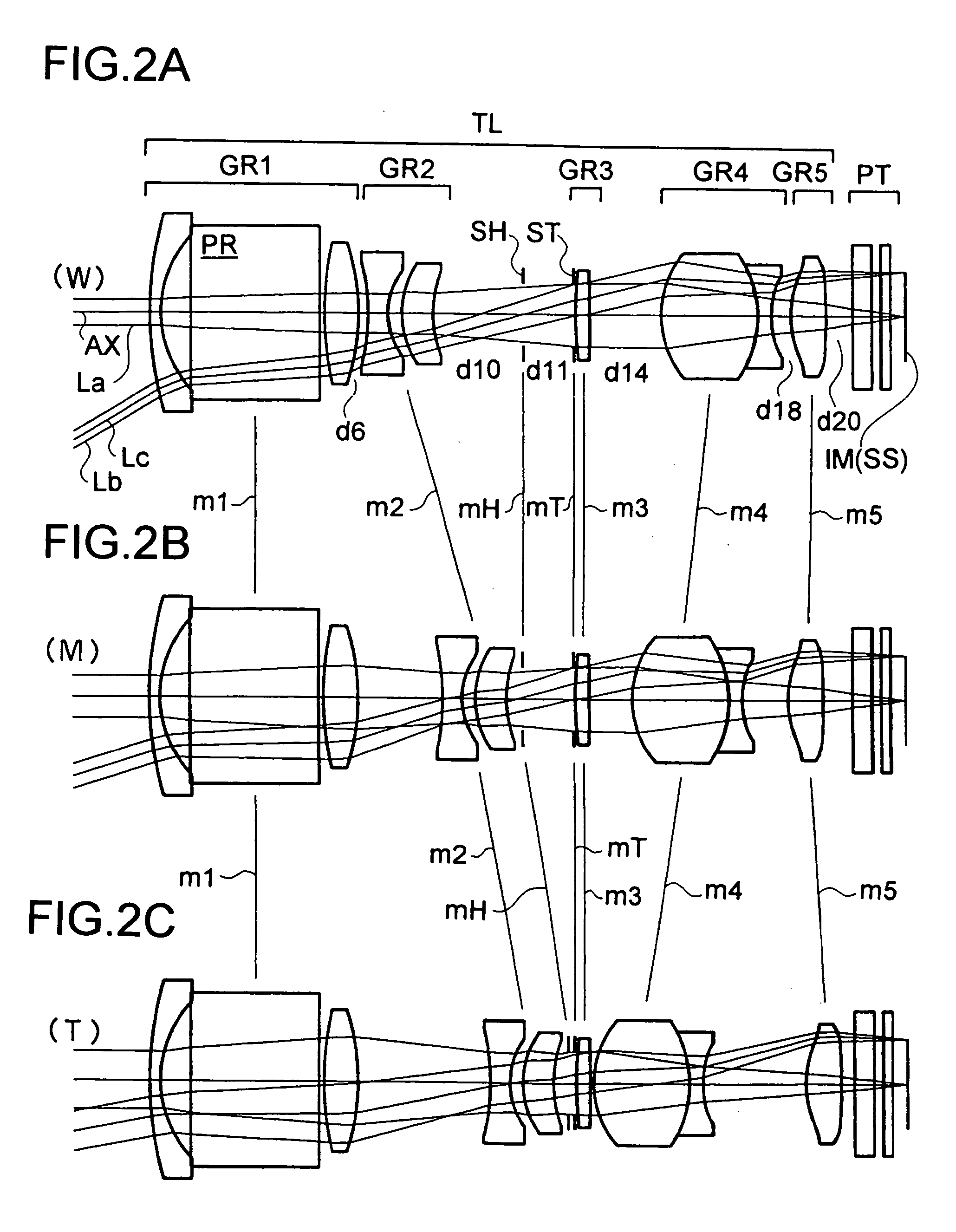
[0090] Hereinafter, the construction and other features of practical examples of the zoom lens systems used in the optical apparatus embodying the present invention will be presented with reference to their construction data and other data. Examples 1 to 3 presented below are numerical examples corresponding to the first to third embodiments, respectively, described hereinbefore, and therefore the optical construction diagrams (FIGS. 1A-1C to 3A-3C) of the first to third embodiments show the lens construction of Examples 1 to 3, respectively.

[0091] Tables 1 to 6 show the construction data of Examples 1 to 3. Table 7 shows the values of the conditional formulae and the data related thereto as actually observed in each example. In the basic optical structures (with “i” representing the surface number) presented in Tables 1, 3 and 5, ri (i=1, 2, 3, . . . ) represents the radius of curvature (in mm) of the i-th surface counted from the object side, and di (i=1, 2, 3, . . . ) represents...


PUM


Abstract

In an optical apparatus provided with: a variable focal length lens system including a plurality of lens units and performing magnification variation by moving at least one lens unit along the optical axis; and an image sensor that converts an optical image formed by the variable focal length lens system into an electric signal, the shutter is disposed to the object side of the most image side lens unit, the aperture stop that determines the f-number is disposed separately from the shutter, and a magnification variation range where the distance between the shutter and the aperture stop varies with magnification variation is provided.

Description

[0001] This application is based on Japanese Patent Application No. 2004-190660 filed on Jun. 29, 2004, the contents of which are hereby incorporated by reference. BACKGROUND OF THE INVENTION [0002] 1. Field of the Invention [0003] The present invention relates to an optical apparatus, and more specifically, to an optical apparatus that optically captures an image of a subject by a taking lens system and outputs it as an electric signal by an image sensor, above all, an image-taking apparatus having a compact and thin variable focal length lens system (for example, a zoom lens system) and a camera (for example, a small-size digital camera) having the image-taking apparatus. [0004] 2. Description of Related Art [0005] In recent years, digital still cameras and video cameras capable of optical zooming have been reduced in size. For this reason, image-taking apparatuses provided therein are required to be compact and thin. Moreover, demand has been rising for a compact image-taking app...

Claims


Application Information

Patent Timeline
Patent Type & Authority Applications(United States)
IPC IPC(8): G02B15/177G03B9/08G03B9/10G03B9/14G03B17/02G03B17/17H04N5/262H04N23/75
CPCG02B5/04G02B15/177H04N5/2254G03B9/14G03B17/17G03B9/10G02B15/143507G02B15/144507
Inventor YAMAGUCHI, SHINJIYAGYU, GENTA
Owner KONICA MINOLTA PHOTO IMAGING
Learn More