
Linear motor, stage apparatus, exposure apparatus, and device manufacturing apparatus

a technology of exposure apparatus and linear motor, which is applied in the direction of magnetic circuit rotating parts, magnetic circuit shape/form/construction, instruments, etc., can solve the problems of linear motor inability to be used, short circuit and damage of coil 1323, and eddy current degrade linear motor characteristics

Inactive Publication Date: 2005-12-29
CANON KK
View PDF17 Cites 46 Cited by
  • Summary
  • Abstract
  • Description
  • Claims
  • Application Information

AI Technical Summary

Benefits of technology

[0017] The present invention has been made in consideration of the above situation, and has as an object to increase, e.g., the cooling efficiency of a linear motor.
[0018] In another aspect, the present invention has an object to prevent, in a vacuum environment, coils of an electromagnetic motor for driving a stage from being damaged due to heat generated by the coils.
[0042] According to the eighth aspect of the present invention, there is provided an EUV exposure apparatus for exposing a pattern of an original plate on an original plate stage to a substrate on a substrate stage in a vacuum environment, the apparatus comprising an electromagnetic motor driving at least one of the original plate stage and the substrate stage, and cooling means for cooling the electromagnetic motor an amount sufficient to prevent overheat damage of the electromagnetic motor resulting from heat generated by the electromagnetic motor.

Problems solved by technology

As a result, the coil 1323 short-circuits and is damaged.
This eddy current degrades linear motor characteristics.
Even if the temperature near the cooling pipe does not reach the application limit temperature of the winding, but the temperature of a portion of the coil where the temperature becomes highest reaches the application limit temperature, the linear motor cannot be used.
Note that the cooling pipe cannot be arranged at the upper portion owing to the above-mentioned problem of generating an eddy current.
If the current is increased to obtain the same thrust, the heat generation amount of the coil 1323 increases by the square of the current, resulting in a very low efficiency.
However, the movable element becomes heavy and requires a larger thrust for movement.
Thus, the structure of FIG. 15 is not optimal.
This method can cool the coil in air even with a low efficiency.
However, heat cannot be dissipated by air in a linear motor used for a recently demanded step & scan projection exposure apparatus which operates in a vacuum environment and uses EUV (Extreme Ultra Violet) light as exposure illumination light, because this linear motor is set in a vacuum environment.
One factor impeding the stage performance of each of the mask stage and the wafer stage is deformation of the structure caused by heat.
Even when a wafer support member and a mask support member constituting parts of the respective stages are each formed of a material exhibiting low thermal expansion, such as SiC, the stage performance is potentially affected unless temperature control is performed at an accuracy level of not larger than 0.001° C. Also, when the wafer and the mask are moved at a high acceleration for the purpose of a higher throughput, heat generated by an electromagnetic motor, e.g., a linear motor for driving the stage, gives rise to a problem.
Accordingly, there occurs a problem that the coils of the electromagnetic motor may suffer overheat damage from the heat generated by the coils themselves.

Method used


Image

  • Linear motor, stage apparatus, exposure apparatus, and device manufacturing apparatus
  • Linear motor, stage apparatus, exposure apparatus, and device manufacturing apparatus
  • Linear motor, stage apparatus, exposure apparatus, and device manufacturing apparatus

Examples


Embodiment Construction

[0067] A linear motor according to the present invention is preferable as an actuator in an exposure apparatus, precision processing apparatus, and precision measurement apparatus used to manufacture devices such as a semiconductor device and liquid crystal display device. As for the exposure apparatus, the linear motor according to the present invention can be applied to any one of a scanning exposure apparatus, step & repeat exposure apparatus, and step & scan exposure apparatus.

[0068] The division structure of a coil unit in the linear motor of the present invention is suitable for, e.g., both a moving-magnet linear motor and moving-coil linear motor. That is, the linear motor of the present invention is suitable for an arrangement in which each coil unit of a stator is divided into a plurality of partial coils and a coolant channel (e.g., cooing pipe) is formed in the divided partial coil pipe, and an arrangement in which each coil unit of a movable element is divided into a pl...


PUM


Abstract

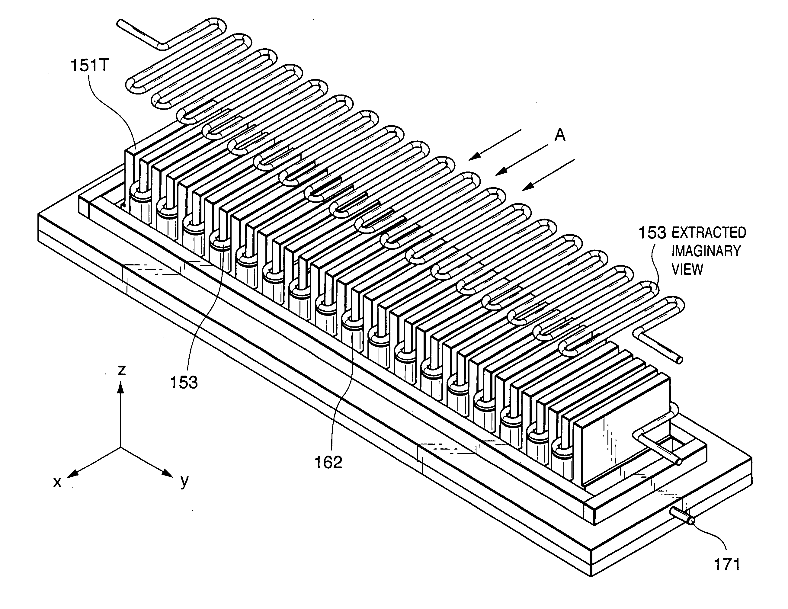
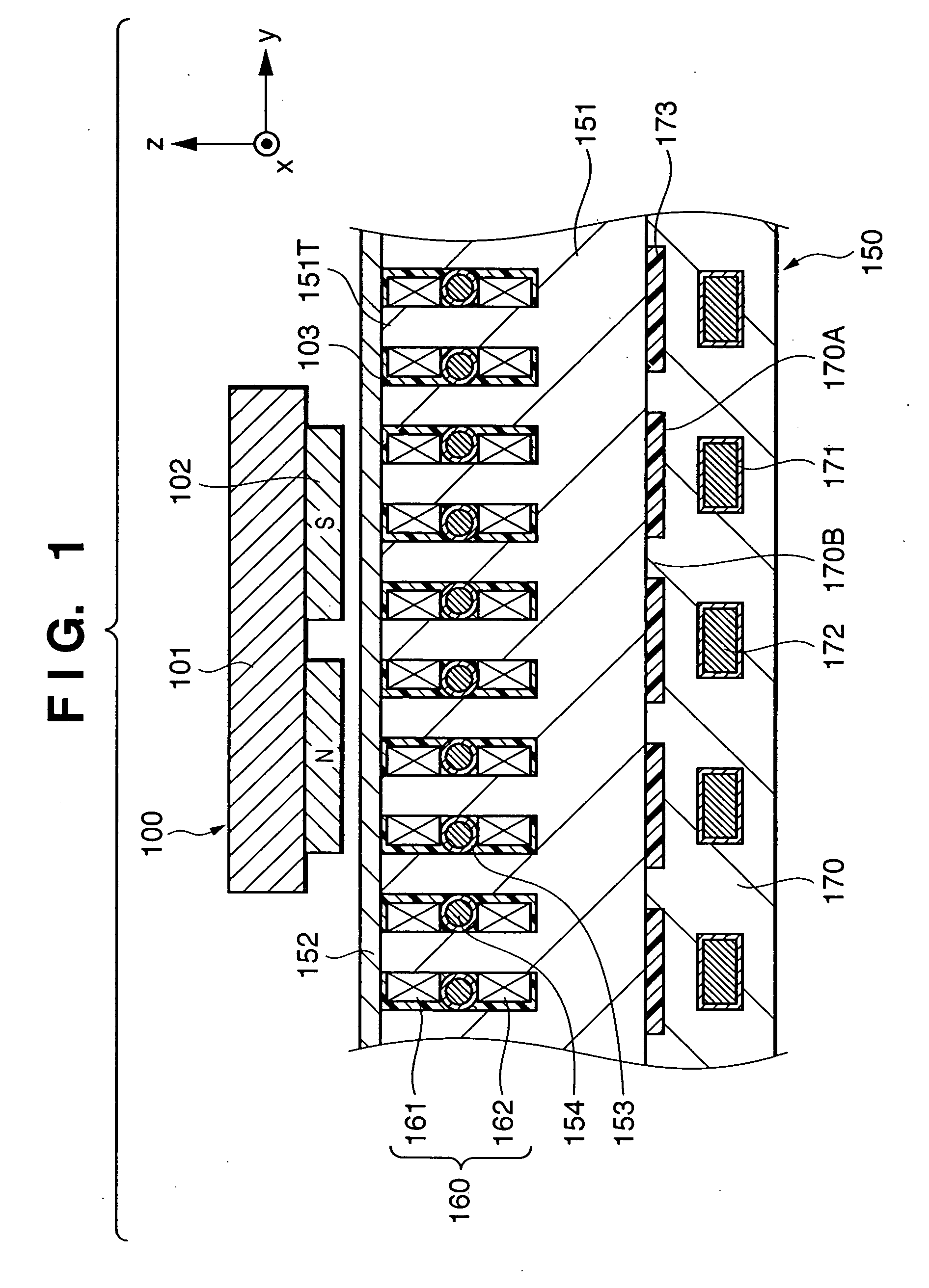
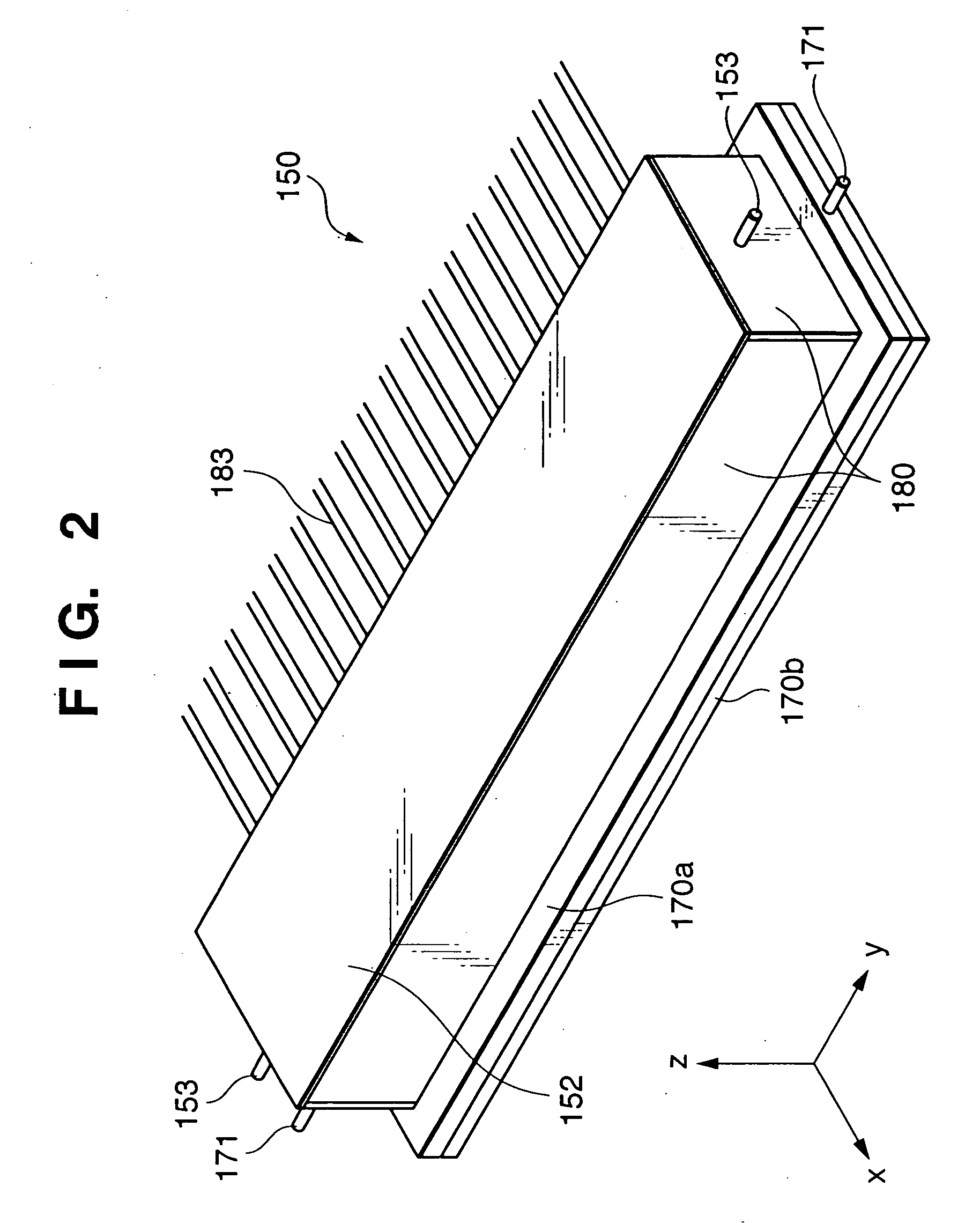
In a linear motor, each arrayed coil unit (160) of a stator yoke (151) is divided into an upper coil (161) and lower coil (162). A cooling pipe (153) is interposed between the upper coil (161) and the lower coil (162).

Description

[0001] This is a continuation-in-part application of U.S. patent application Ser. No. 10 / 347,862 filed on Jan. 22, 2003 entitled “LINEAR MOTOR, STAGE APPARATUS, EXPOSURE APPARATUS, AND DEVICE MANUFACTURING APPARATUS”, and U.S. patent application Ser. No. 10 / 674,359 filed on Oct. 1, 2003 entitled “EUV EXPOSURE APPARATUS WITH COOLING DEVICE TO PREVENT OVERHEAT OF ELECTROMAGNETIC MOTOR IN VACUUM”.FIELD OF THE INVENTION [0002] The present invention relates to a linear motor, a stage apparatus to which the linear motor is applied, an exposure apparatus, and a device manufacturing method to which the exposure apparatus is applied. BACKGROUND OF THE INVENTION [0003]FIG. 13 is a sectional view schematically showing the structure of a conventional general moving-magnet linear motor. A movable element 1310 comprises field permanent magnets 1311 and movable element yoke 1312. The movable element yoke 1312 is arranged on the back surfaces of the permanent magnets 1311. The movable element yoke ...

Claims


Application Information

Patent Timeline
IPC IPC(8): G03F7/20H02K1/22H02K3/24H02K41/00H02K41/03
CPCG03F7/70758H02K41/03H02K3/24
Inventor KUBO, HIROYOSHIEMOTO, KEIJI
Owner CANON KK
Learn More