
Wireless positioning approach using time delay estimates of multipath components

a multi-path component and time delay technology, applied in the field of wireless positioning technique, can solve the problems of inability to achieve optimization, difficult application of ray tracing model used in underwater applications with acoustic positioning scheme to mobile communication channels, and inability to achieve accurate position estimation

Inactive Publication Date: 2005-12-22
NTT DOCOMO INC
View PDF6 Cites 107 Cited by
  • Summary
  • Abstract
  • Description
  • Claims
  • Application Information

AI Technical Summary

Benefits of technology

The present invention provides a wireless positioning scheme that uses the delay estimates of both first arriving and subsequent multipath components in received signals. This is done by selecting useful multipath components from a delay profile that contains a first arriving wave and the subsequent delay waves. The prior information about non-line-of-sight delays is also used to enhance the position accuracy. The invention can locate the position of a mobile station even in a non-synchronous system and in a particular geometry that is not ideal for position estimation. The technical effects of the invention are improved position accuracy and efficiency in wireless positioning.

Problems solved by technology

Locating positions using radio signals that are susceptible to multipath propagation has been an important issue for wideband mobile communication systems.
The conventional techniques disclosed in the above-described publications have some problems.
The ray tracing model used in the underwater application with an acoustic positioning scheme is difficult to apply to mobile communication channels, and cannot achieve optimization.

Method used


Image

  • Wireless positioning approach using time delay estimates of multipath components
  • Wireless positioning approach using time delay estimates of multipath components
  • Wireless positioning approach using time delay estimates of multipath components

Examples


first embodiment

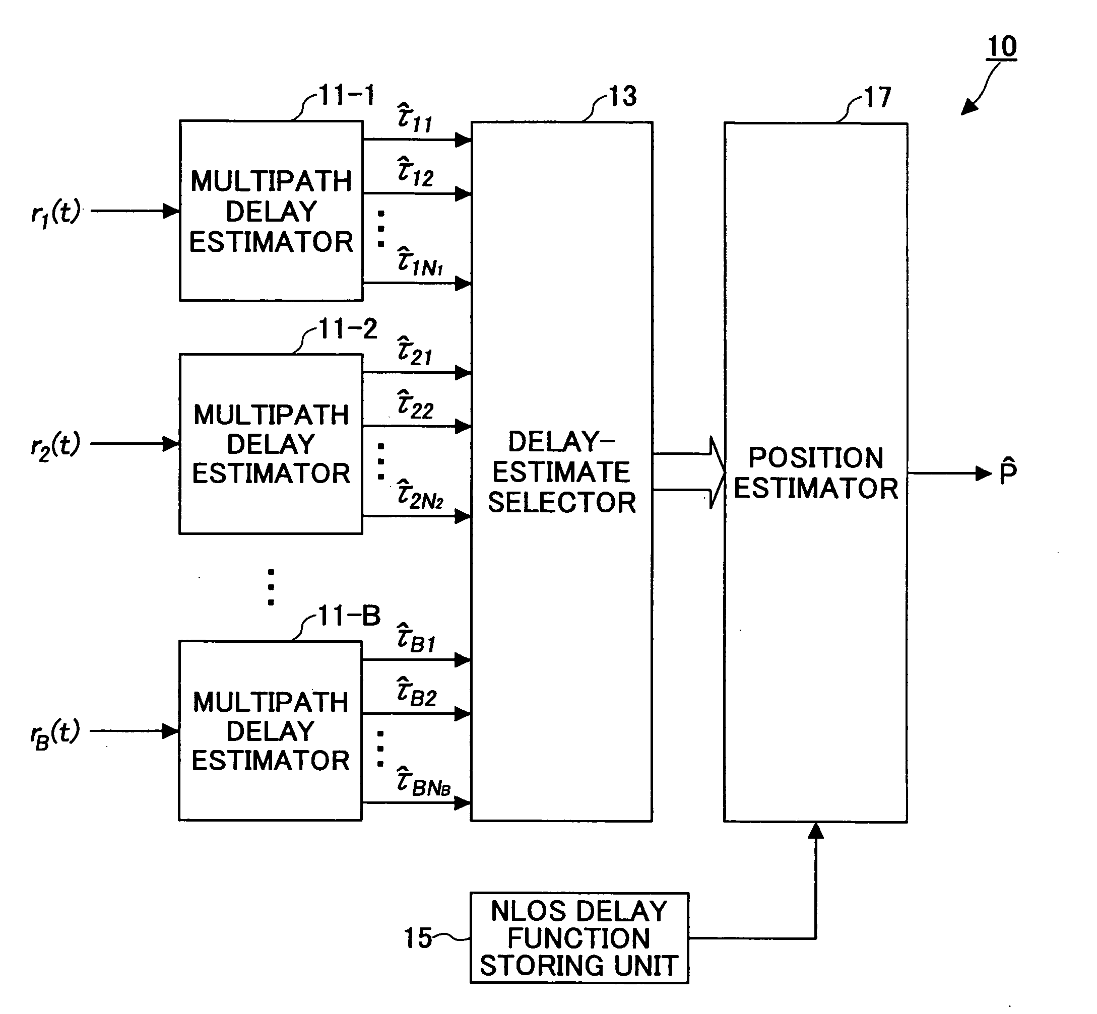
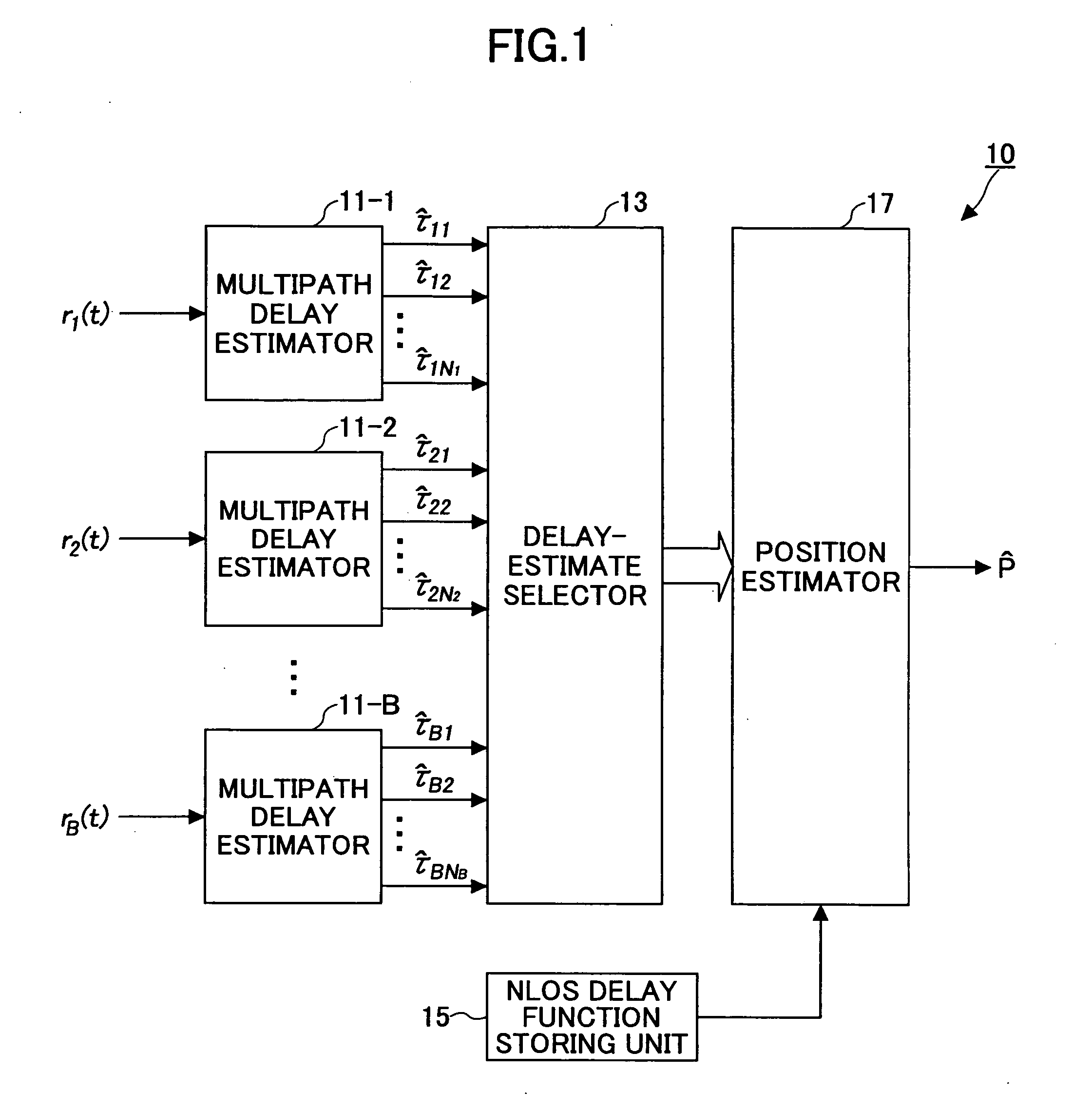
[0045]FIG. 1 is a schematic block diagram of a wireless positioning apparatus according to the first embodiment of the invention. In this embodiment, the positioning scheme is applied to a synchronous system. A wireless positioning apparatus 10 includes multipath delay estimators 11-1, 11-2, . . . , 11-B that receive signals r1(t), r2(t), . . . , rB(t), respectively. Each of the multipath delay estimators 11-1 through 11-B is configured to estimate multipath delay components from the associated received signal. The multipath delay estimators 11-1 through 11-B may be treated collectively as a multipath delay estimator 11.

[0046] The wireless positioning apparatus 10 also includes a delay-estimate selector 13 (which may be referred to simply as “selector 13”) that selects appropriate delay estimates from the multipath delay components according to a predetermined criterion, an NLOS delay function storing unit 15 that stores an NLOS delay function defining prior information about non-l...

second embodiment

[0070] Next, the second embodiment of the present invention is described in conjunction with FIG. 6 and FIG. 7. In the second embodiment, the wireless positioning technique is applied to a non-synchronous system. FIG. 6 is a schematic block diagram of a wireless positioning apparatus 50, and FIG. 7 is a flowchart showing the operation performed by the wireless positioning apparatus 50.

[0071] The wireless positioning apparatus 50 includes multipath delay estimators 51-1, 51-2, . . . , 51-B that receive signals r1(t), r2(t), . . . , rB(t), respectively. Each of the multipath delay estimators 51-1 through 51-B is configured to estimate multipath delay components from the received signal. The wireless positioning apparatus 50 also includes a selector 53 that selects appropriate delay estimates from the multipath delay components according to a predetermined criterion, a TDOA data generator 54 configured to generate time-difference-of-arrival (TDOA) data based on the selected delay esti...

third embodiment

[0079] Next, the third embodiment of the present invention is described with reference to FIG. 8 through FIG. 10. In the previous embodiments, the position of the mobile station is estimated based on useful multipath delay components selected from multipath delay profiles of received signals at multiple base stations. This method is based on the premise that there are enough base stations involved in position estimation.

[0080] The third embodiment is designed to still allow time-delay based position estimation to a certain degree of accuracy even in unfavorable MS-BS layouts that generally do not allow position estimation using received signals. Such unfavorable MS-BS layouts include a case in which the number of base stations available for position estimation is two or less.

[0081] The following two cases in particular MS-BS geometry are observed.


PUM


Abstract

A wireless positioning apparatus (10, 30, 50) includes a multipath delay estimator (11) configured to estimate multipath delay components from one or more received signals; a selector (13, 53) configured to select appropriate delay estimates from the estimated multipath delay components according to a predetermined criterion; a storage (15, 55) configured to store an NLOS delay function defining prior (statistics of) information about non-line-of-sight delays; and a position estimator (17, 57) configured to estimate a position of a mobile station based on the selected delay estimates and the NLOS delay function read out from the storage.

Description

FIELD OF THE INVENTION [0001] The present invention relates to a wireless positioning technique, and more particularly, to locating the position of a mobile station (MS) by processing the delay estimates of the radio signals that travel between the mobile station (MS) and several base stations (BSs). BACKGROUND OF THE INVENITON [0002] In a multipath environment, multipath echoes originating from the same transmission signal arrive at a receiving point through different paths due to reflection from a tall building or diffraction by the straight edge or the corner of an obstruction. Accordingly, a received signal contains a direct wave propagating through a straight (the shortest) path, followed by delayed waves arriving slightly after the direct wave. Radio communication that can expect a direct wave is called line-of-sight (LOS) communication because of the straight path between transmission and receiving antennas along a visual line of sight. In contrast, radio communication that c...

Claims


Application Information

Patent Timeline
Patent Type & Authority Applications(United States)
IPC IPC(8): H04W64/00
CPCH04W64/00
Inventor QI, YIHONGSUDA, HIROHITOASAI, TAKAHIRO
Owner NTT DOCOMO INC
Learn More