
Gas-liquid contact tray with fixed valves for mass transfer

a technology of fixed valves and gas-liquid contact trays, which is applied in the direction of machines/engines, combustion-air/fuel-air treatment, and separation processes, etc., can solve the problems of low processing capacity, too much liquid entrainment, and too much liquid weeping, so as to achieve low liquid entrainment and low liquid weeping

Inactive Publication Date: 2005-12-22
CHINA PETROCHEMICAL CORP +1
View PDF20 Cites 38 Cited by
  • Summary
  • Abstract
  • Description
  • Claims
  • Application Information

AI Technical Summary

Benefits of technology

[0006] Thus, one object of the present invention is to provide a gas-liquid contact tray with fixed valves for mass transfer, which has a low liquid entrainment and low liquid weeping.
[0007] Another object of the present invention is to provide a gas-liquid contact tray with fixed valves for mass transfer, which has a high mass transfer capacity and good turn-down characteristics.
[0008] Another object of the present invention is to provide a gas-liquid contact tray with fixed valves for mass transfer, which has a simple structure and a low cost.

Problems solved by technology

The tray with perforations has advantages of low pressure drop, few choke, easy making, low cost, and no maintenance, but also has disadvantages of too much liquid entrainment, too much liquid weeping, low processing capacity and low mass transfer efficiency.
The tray with floating valves overcome the disadvantages of the tray with perforations, has advantages of high processing capacity, low liquid entrainment, low liquid weeping, and high mass transfer efficiency, but also has disadvantages of too much necessary raw materials, high manufacturing cost, easy choke, low working reliability.
Unfortunately, in these patents, the gas flow or jet is horizontally blew off from the side openings of each fixed valve and then is blew into the liquid layer, forming a face-to-face impinging flow between any two adjacent fixed valves with the gas being blew off from the side opening of another fixed valve (see FIG. 15).
The impinging jets 28 not only cause the liquid splash upward from the tray deck, thus forming more liquid entrainment and lowering the mass transfer capacity, but also consume more energy and increase the pressure drop of the tray

Method used


Image

  • Gas-liquid contact tray with fixed valves for mass transfer
  • Gas-liquid contact tray with fixed valves for mass transfer
  • Gas-liquid contact tray with fixed valves for mass transfer

Examples


Embodiment Construction

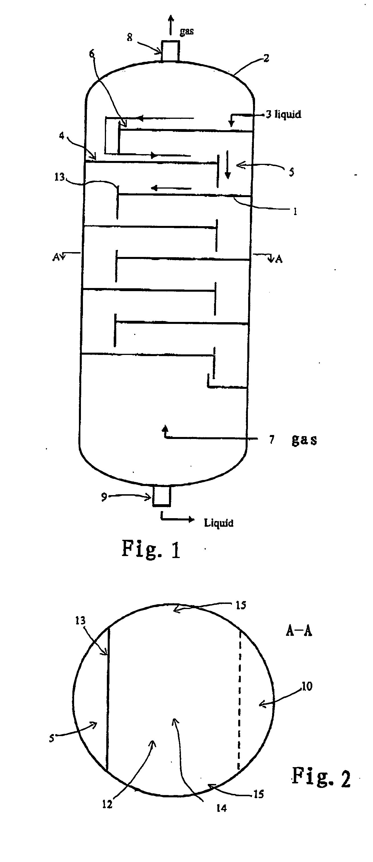
[0052]FIG. 1 schematically shows the basic environment of cross-flow trays constructed according to the present invention, in which a plurality of horizontal trays 1 are mounted in a vertical tower 2 and are vertically spaced from each other. Liquid is fed to the upstream end 4 of the uppermost tray by a liquid supply line 3. Down-corner passages 5 (downcorner called thereafter) lead the liquid from the downstream end 6 of an upper tray to the upstream end 4 of the next lower tray. Gas is introduced into the lower end of the tower by a gas supply line 7. The gas will ascend through the tower, passing up the bubbling elements (i.e. the fixed valves and perforations as defined thereafter) of the tray and going into the liquid on the trays. The tower has a vapor outlet 8 at its upper end, and a liquid outlet 9 at its lower end.

[0053] The tray with fixed valves according to the present invention is to increase mass transfer efficiency and increase processing capacity. The proportions o...


PUM


Abstract

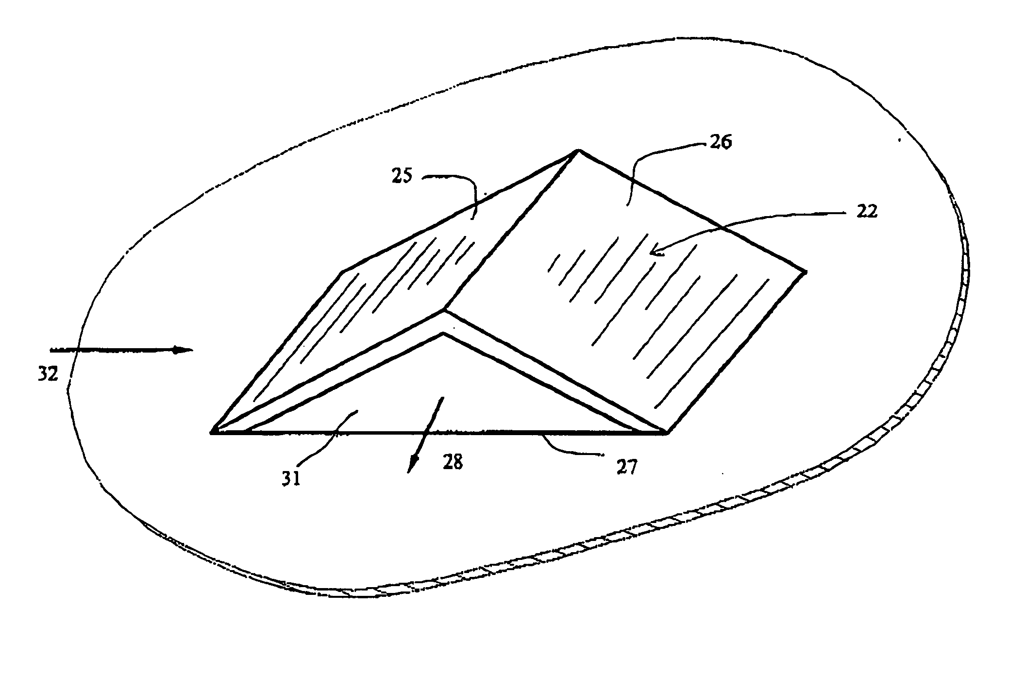
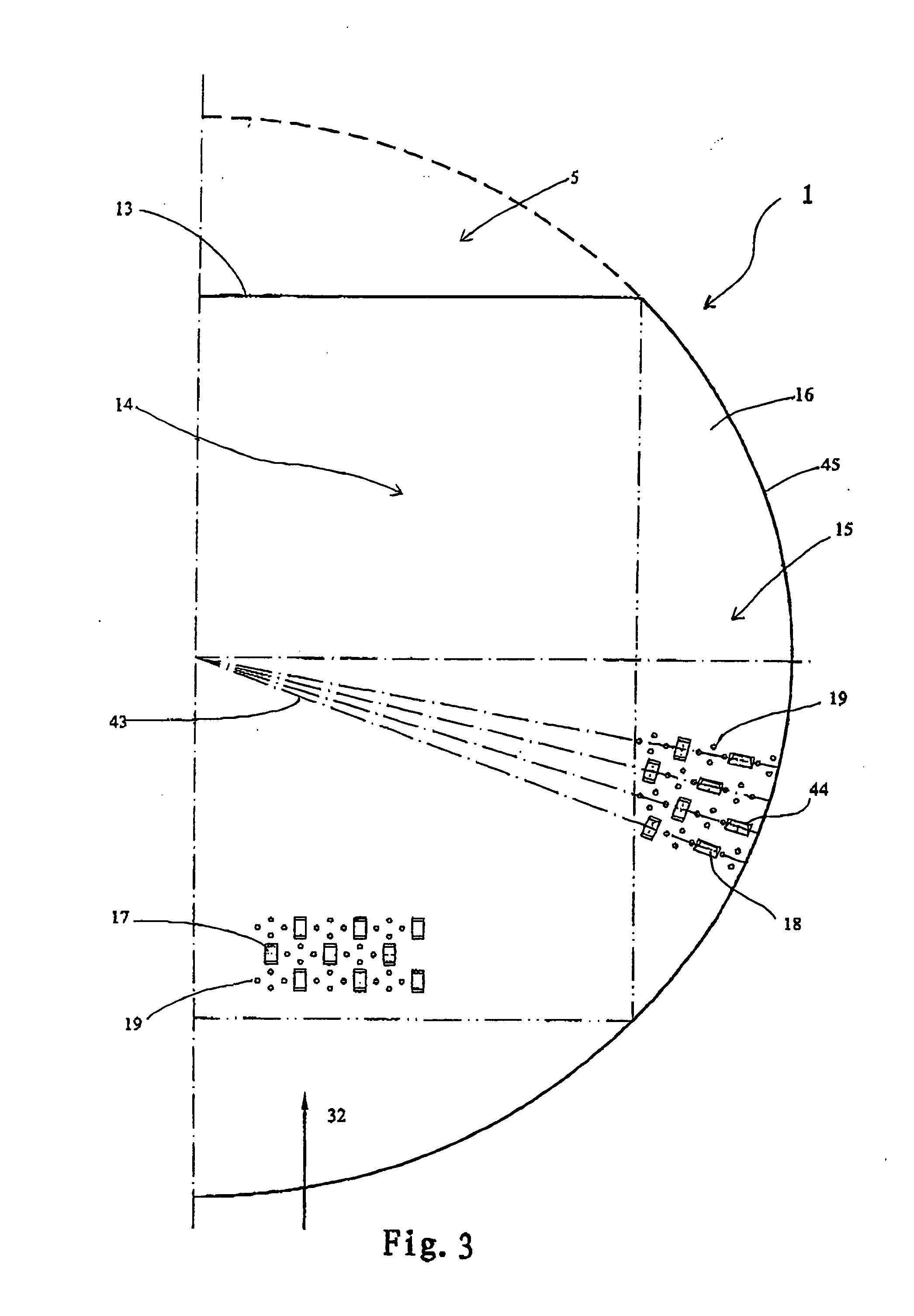
A gas-liquid contact tray with fixed valves for mass transfer, in which the fixed valve comprising an upstream portion, a midportion and a downstream portion is made by punch from the tray deck so as to form as a deflector, and the upstream portion and the downstream portion are integrated with the tray deck, characterized in that said midportion has a central plane portion and downward inclined margins, and the tray deck is further provided with perforations which are arranged between the fixed valves adjacent in the liquid flow direction. The gas-liquid contact tray with fixed valves for mass transfer according to the present invention has a low liquid entrainment, low liquid weeping, a high mass transfer capacity and good turn-down characteristics.

Description

FIELD OF THE INVENTION [0001] The present invention relates to a gas-liquid contact tray with fixed valves for mass transfer. The tray is used for the fractional distillation columns, the absorption columns, or the adsorption columns in the oil refining industry, the chemistry industry, the petrochemistry industry, the light industry, or the like. PRIOR ART [0002] Before the present invention, there have been developed the tray with perforations, the tray with floating valves, and the tray with fixed valves. [0003] The tray with perforations has advantages of low pressure drop, few choke, easy making, low cost, and no maintenance, but also has disadvantages of too much liquid entrainment, too much liquid weeping, low processing capacity and low mass transfer efficiency. [0004] The tray with floating valves overcome the disadvantages of the tray with perforations, has advantages of high processing capacity, low liquid entrainment, low liquid weeping, and high mass transfer efficiency...

Claims


Application Information

Patent Timeline
IPC IPC(8): B01D3/16B01D3/22B01F3/04
CPCB01D3/22B01D3/163
Inventor YAO, KEJIANWANG, LIANGHUAYU, XIAOMEI
Owner CHINA PETROCHEMICAL CORP
Learn More