
Snap hook

Active Publication Date: 2005-12-22
COASTAL PET PROD
View PDF15 Cites 3 Cited by
  • Summary
  • Abstract
  • Description
  • Claims
  • Application Information

AI Technical Summary

Benefits of technology

[0004] A primary object of the present invention is to provide an improved snap hook, or bolt snap. Other objects are to provide a snap hook that is easy to attach and remove from an object such as a pet collar ring; to provide a snap hook that is easy to grasp and hold in a desired position; to provide a snap hook that is convenient and easy to open but that resists inadvertent opening; to provide a snap hook that avoids snagging of a ring or other object in the hook; to provide a snap hook which avoids injury to the user; and to provide a snap hook that overcomes disadvantages of known snap hooks and bolt snaps.

Problems solved by technology

The conventional snap hook is subject to disadvantages that can be appreciated by considering the use of a snap hook with a pet leash.
One problem is that the lock pin of a typical snap hook is difficult to manipulate.
The axially movable slider button projection is small and hard to manipulate.
In addition, the eye is typically pivotable or swiveled relative to the hook so that it is hard to hold the snap hook in a desired position.
The slender cylindrical shape of the conventional snap hook adds to this difficulty.
The axial force required to move the lock pin, resulting from friction and the bias spring force, can be difficult for the user to apply to the small lock pin slider button.
After the lock pin is open, it can be hard to attach the hook to a collar ring because the projection and thus the user's hand are close to the hook and block the view of the hook.
Removal of the snap hook is also difficult for the same reasons and also because the collar ring can hang up or snag in the hook.

Method used


Image

  • Snap hook
  • Snap hook
  • Snap hook

Examples


Embodiment Construction

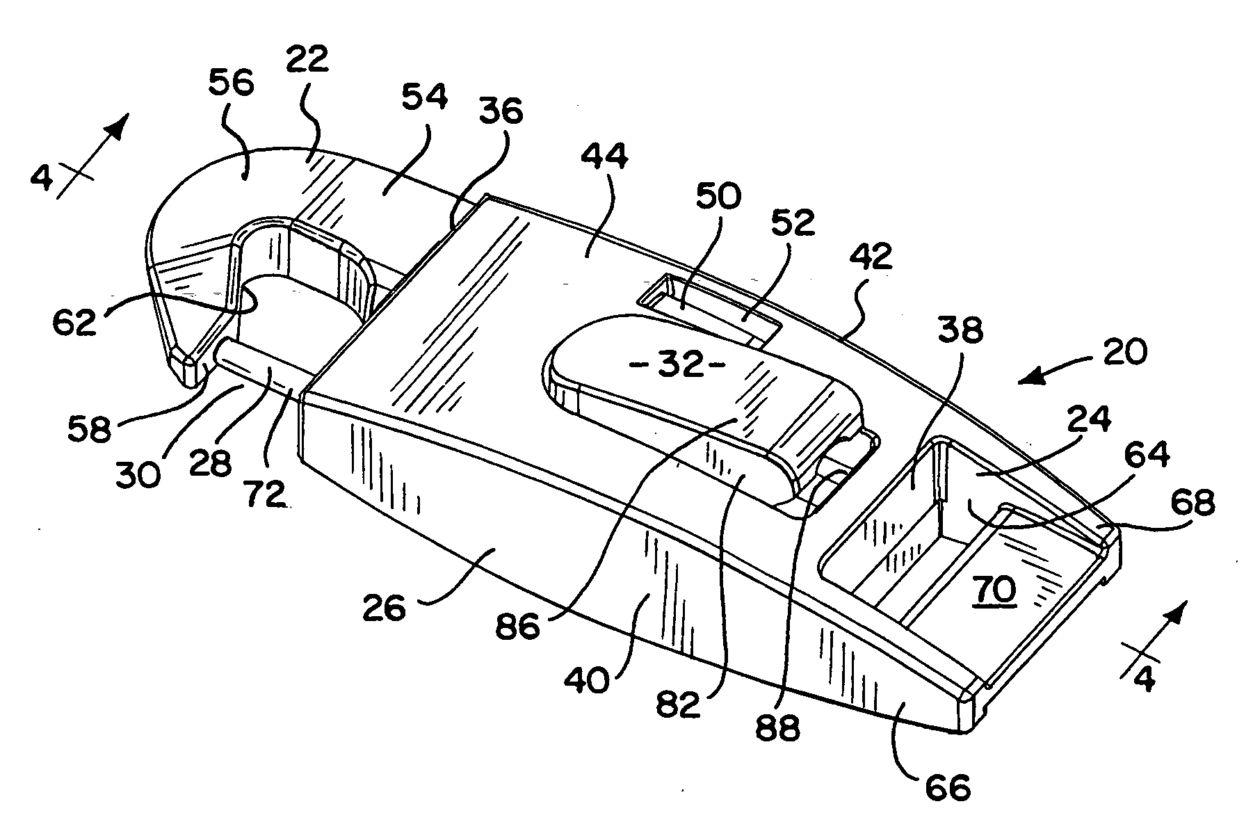
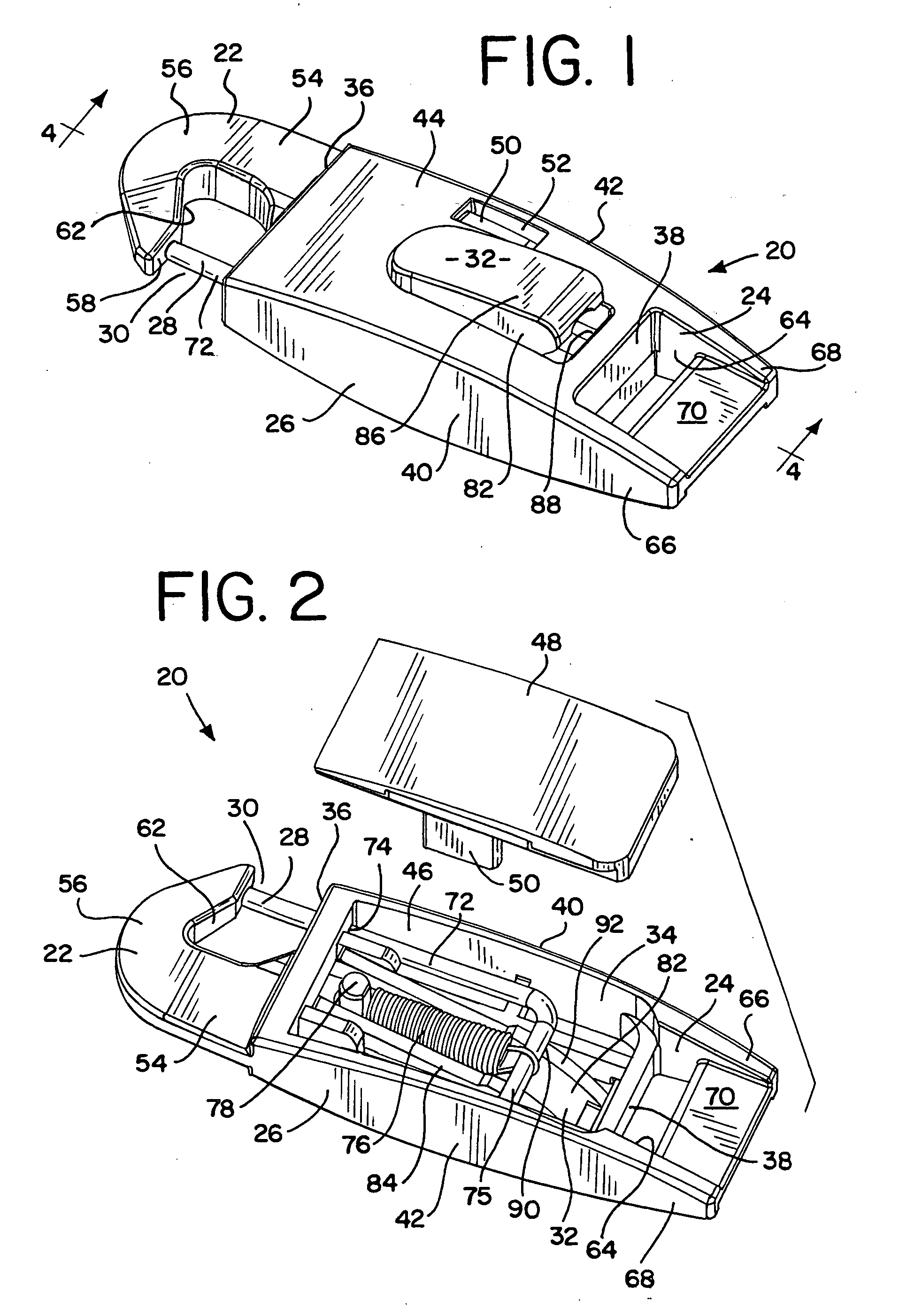
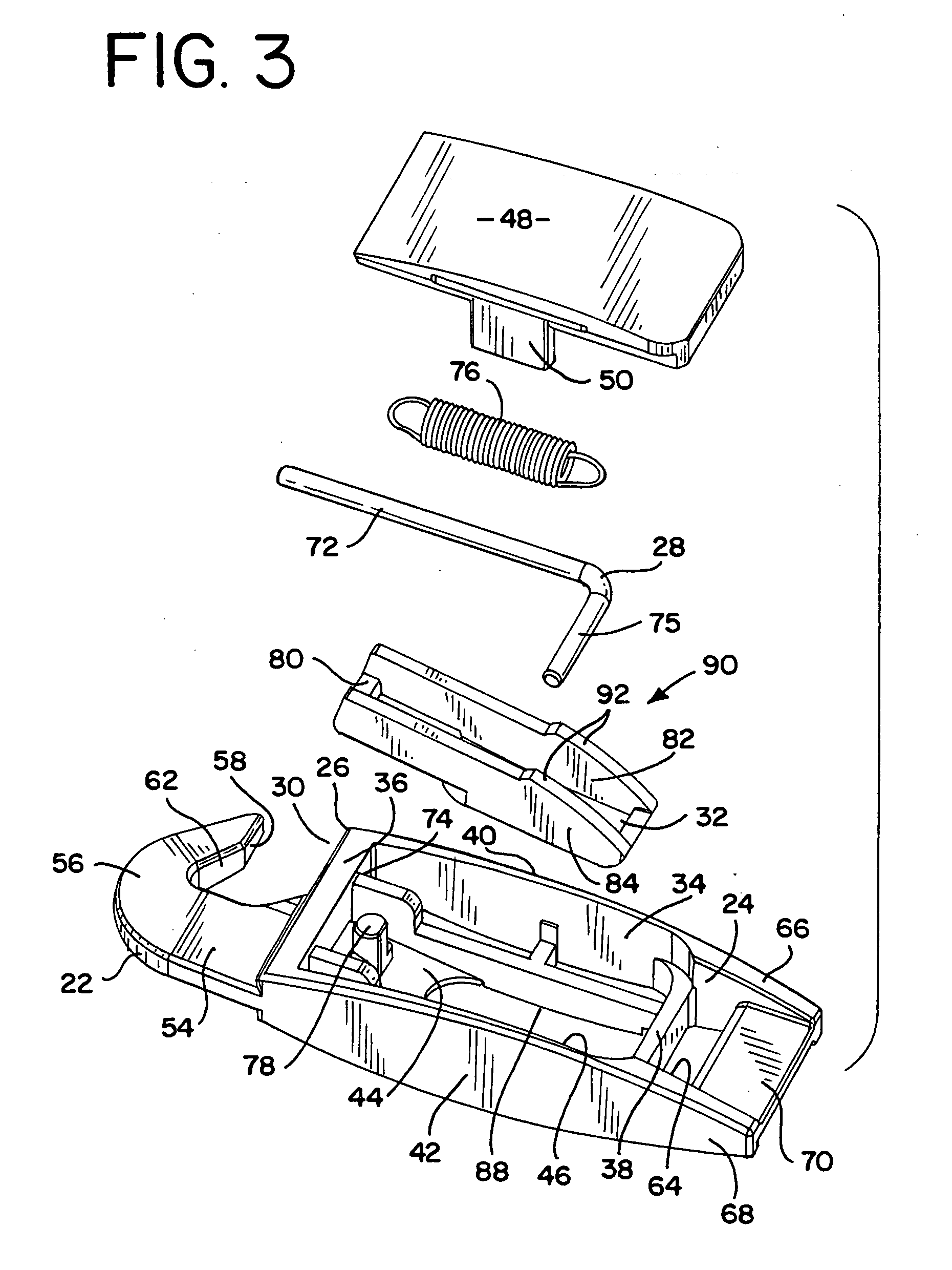
[0013] Having reference now to the drawing, there is illustrated a snap hook, or bolt snap, generally designated as 20 and constructed in accordance with the principles of the present invention. In general the snap hook 20 includes a hook 22 and an eye 24 disposed at opposite ends of a body 26. A lock pin 28 is movable in the direction of the longitudinal axis of the body 26 to open or close a mouth 30 of the hook 22. A button 32 is pressed to retract the lock pin 28 and open the

[0014] Preferably the body 26 is made of a strong molded plastic material such as glass reinforced nylon. The hook 22 and the eye 24 are integral parts of the body 26, made as a single molded part in a single molding operation, so that the body 20, hook 22 and eye 24 are one homogeneous piece. The eye 24 is integral with and thus nonrotationally fixed to the body 26, making the body 26 easier for a user to hold an manipulate.

[0015] The body 26 is hollow and has a central cavity 34 located between end walls...


PUM


Abstract

A hook and an eye are integral with and located at opposite longitudinal ends of a body. The hook includes a tip spaced from the body and defining a mouth for attachment of the hook to a ring or other object. A lock pin mounted in the body moves axially between a closed position engaging the tip of the hook and an open position. The body has a flat, easily gripped shape with a button at one side movable in a transverse direction. A cam system translates transverse button movement into axial movement of the lock pin, and provides a decreasing force-displacement characteristic. The hook is designed to break to prevent user injury in the event of excessive force, and includes a ramp surface facilitating detachment of the hook.

Description

FIELD OF THE INVENTION [0001] The present invention relates to an improved snap hook, or bolt snap. DESCRIPTION OF THE PRIOR ART [0002] A snap hook, also called a bolt snap, is a fastening and connecting device having numerous uses in applications where it is desired to connect a line, leash, cord, wire or the like to a ring or loop or other object. For example, a snap hook is used to releasably attach a pet leash to a D ring on a collar of a dog. A snap hook has a hook at one end and an eye at the opposite end. A lock pin or other device closes the mouth of the hook to prevent inadvertent release of a ring or other object to which the hook is attached. A mechanism is typically provided for manual release of the lock pin. A widely used type of snap hook includes a spring biased, axially movable lock pin that is manipulated by a small slider button projection near the hook that is moved axially by the user's thumb. U.S. Pat. Nos. 697,367 and 824,179 disclose versions of the conventio...

Claims


Application Information

Patent Timeline
IPC IPC(8): A01K27/00F16B45/04
CPCA01K27/005Y10T24/45398F16B45/04F16B45/049
Inventor JOHNSON, DWIGHT N.
Owner COASTAL PET PROD
Learn More