
System and method for onboard detection of ballistic threats to aircraft

a technology for aircraft and ballistic threats, applied in the field of airborne threat monitoring systems, can solve the problems of non-military applications, no widespread use of shoulder-fired munitions, and the cost of upgrading for non-military applications

Inactive Publication Date: 2005-12-15
MDA INFORMATION SYST
View PDF26 Cites 56 Cited by
  • Summary
  • Abstract
  • Description
  • Claims
  • Application Information

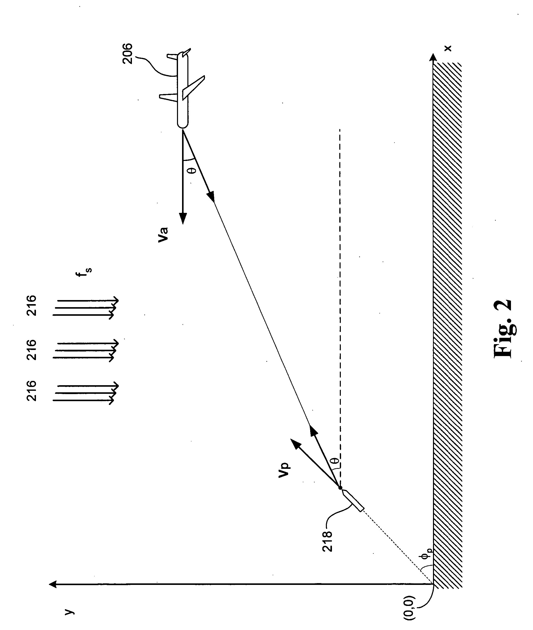
AI Technical Summary

Benefits of technology

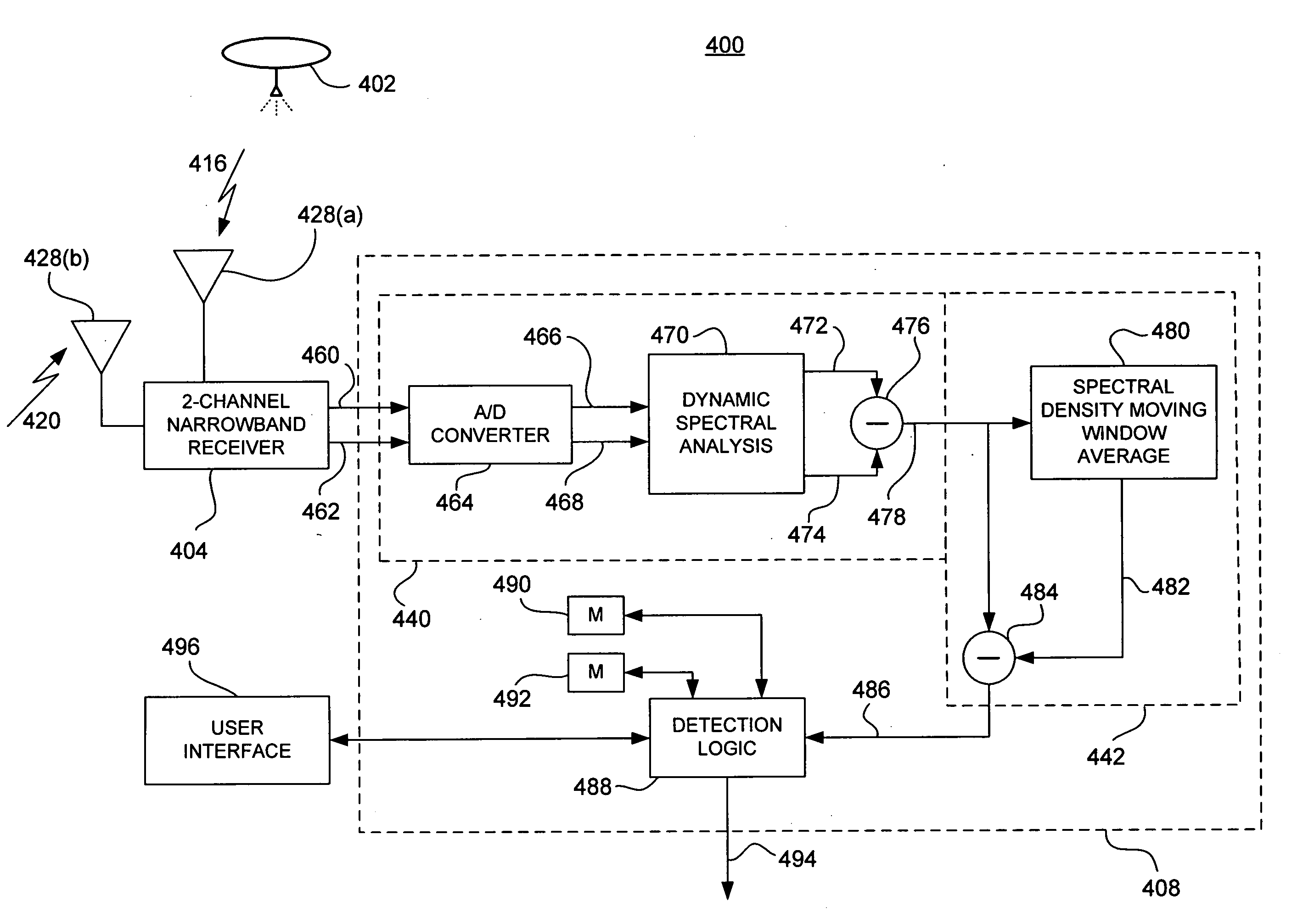
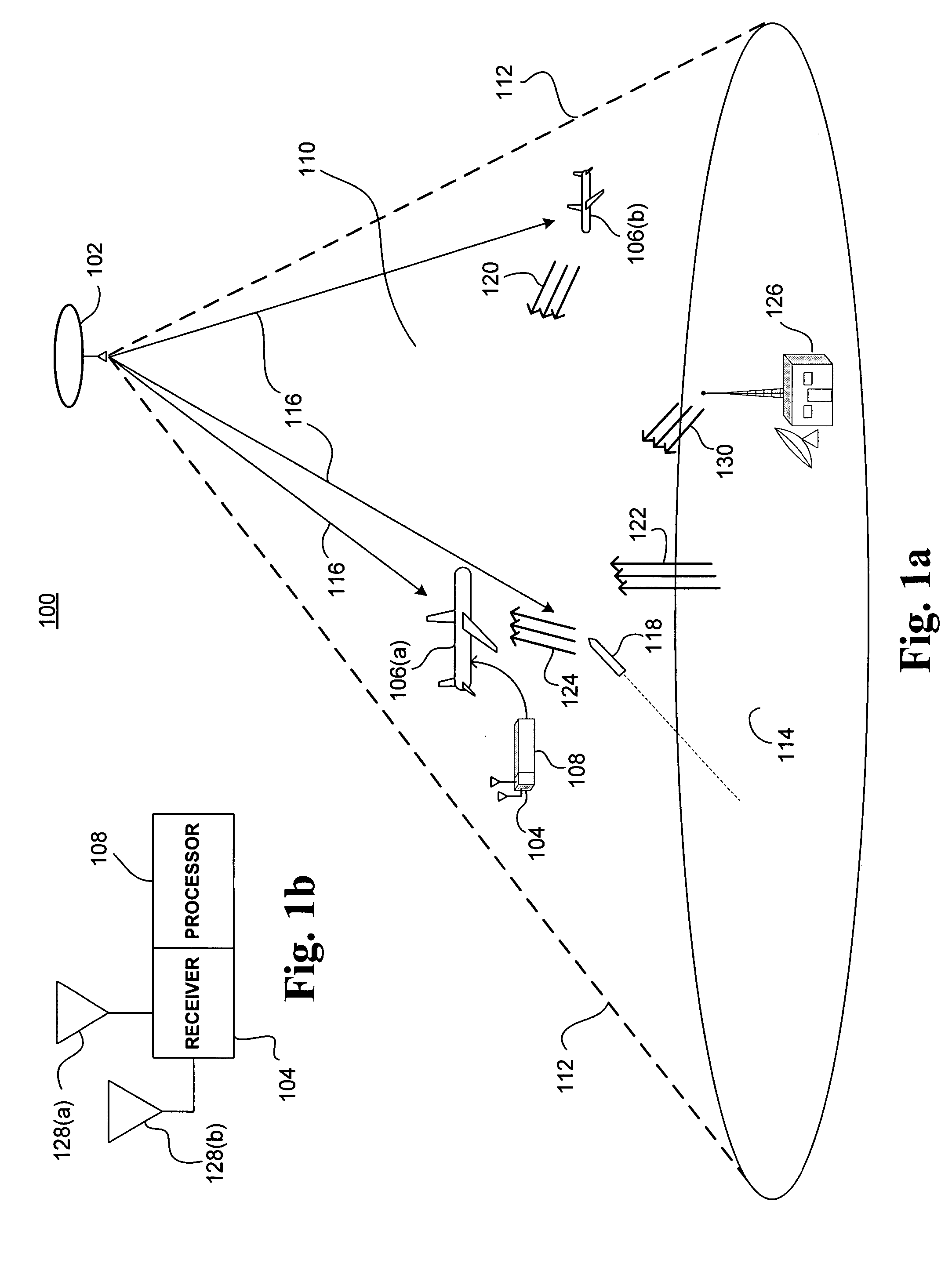
[0008] The present invention addresses such a solution by providing civilian and military aircraft with a low-cost means to rapidly determine an imminent threat from an incoming ballistic projectile (e.g. a shoulder launched missile). The invention applies a wide area radio frequency (RF) illumination that is shared among a large number of defended aircraft. Each aircraft requires only a passive receiver and a signal processor that exploits narrow-band Doppler scattering effects to implement an onboard missile threat detection system.
[0010] One object of the present invention is to minimize the per-aircraft cost of implementing a countermeasure system for ballistic threats to aircraft. This is achieved through application of a bi-static collection geometry that separates the transmitting and receiving antennas. Thus, each aircraft requires only a passive, receive-only radar detection system, and each receive-only system responds to the same active RF transmitter that illuminates a broad field of airspace shared among all aircraft in the fleet.
[0011] Another object of the invention is to exploit narrow-band Doppler induced frequency shifts of projectile-scattered RF energy to determine the presence of a ballistic threat. Another object of the invention is the application of unique algorithms for efficient determination of ballistic threats.
[0013] Another object of the present invention is to apply moving-window, time integration of a dynamic Doppler history to establish a slowly varying spectral background. This allows for an accurate calculation of a moving average of background noise, which, when subsequently removed, enables better detection of transient missile signatures. Another object of the invention is to apply source modulation schemes to improve detection of desired scatter signals against the RF background of terrestrial sources.
[0014] The present invention provides many advantages over existing projectile detection systems. One advantage is the ability to centrally control illumination parameters such as beamwidth, power level, frequency, modulation waveform, polarization, and source location. Another advantage is an ability to enhance performance characteristics such as operating range, probability of detection, and accuracy, over a wide range of operational situations. Another advantage is a lower per-aircraft system cost. Another advantage is an ability to detect projectiles with low radar cross section (RCS), such as non-metallic projectiles, by exploiting scatter mechanisms induced, for example, by shockwave air pressure gradients. A further advantage is the ability to detect airborne threats through cloud cover.

Problems solved by technology

In the hands of terrorists, shoulder-fired munitions such as these represent a serious security threat to civilian aircraft.
A number of approaches that address this problem have been explored, but none have been successfully developed for widespread use.
One major obstacle to development of any of the aforementioned missile warning and countermeasure systems for non-military applications is the cost of upgrading.
Owners and operators of civilian and small commercial aircraft enterprises are not able to afford the costs of such sophisticated protection systems.
In other cases, spatial considerations may discourage installation of a warning and countermeasure system on an aircraft where the availability of space for retrofit systems is already at a premium.
A practical solution to counter ballistic threats to civilian aircraft has yet to be fully developed.

Method used


Image

  • System and method for onboard detection of ballistic threats to aircraft
  • System and method for onboard detection of ballistic threats to aircraft
  • System and method for onboard detection of ballistic threats to aircraft

Examples


Embodiment Construction

[0026] As utilized herein, terms such as “about” and “substantially” and “near” are intended to allow some leeway in mathematical exactness to account for tolerances that are acceptable in the trade. Any deviations upward or downward from the value modified by the terms “about” or “substantially” or “near” in the range of 1% to 20% or less should be considered to be explicitly within the scope of the stated value. Accordingly, two parts are “substantially similar” if a comparison between the two yields at least 80% commonality in a selected characteristic.

[0027] As used herein, the term “software” includes source code, assembly language code, binary code, firmware, macro-instructions, micro-instructions, or the like, or any combination of two or more of the foregoing.

[0028] The term “memory” refers to any processor-readable medium, including but not limited to RAM, ROM, EPROM, PROM, EEPROM, disk, floppy disk, hard disk, CD-ROM, DVD, or the like, or any combination of two or more o...


PUM


Abstract

A bi-static continuous wave radar system and related methods for detecting incoming threats from ballistic projectiles includes a remote source of RF illumination, and a local receiver installed in one or more target aircraft. A first receiving channel acquires direct path illumination from the source and provides a reference signal, and a second receiving channel acquires a scatter signal reflected by a projectile. A processor coupled to each receiver corrects scatter signal Doppler offset induced by relative source motion, isolates narrowband Doppler signals to derive signatures characteristic of the projectile, and by executing appropriate algorithms, compares the derived signatures to modeled signatures stored in memory. If the comparison yields a substantial similarity, the processor outputs a warning signal sufficient to initiate defensive countermeasures.

Description

BACKGROUND OF THE INVENTION [0001] 1. Field of the Invention [0002] This invention relates generally to airborne threat monitoring systems, and more specifically to systems employing bi-static continuous wave radar to enable an aircraft to sense incoming ballistic threats and initiate responsive countermeasures. [0003] 2. Related Art [0004] The evolving face of global terrorism has crystallized the threat that inexpensive and readily available shoulder-fired missiles can be directed against civilian aircraft. The FBI estimates that since 1989, more than 50,000 shoulder-fired missiles, or MANPADS (man-portable air-defense systems), have been sold to third-world countries, and that from 1978-1998, 29 civilian planes have been shot down by shoulder-fired missiles. More recently, the war in Iraq has provided a proving ground for this tactic, where terrorist militia have struck at least twelve aircraft with shoulder-fired missiles in a three-month time period from October 2003 to January...

Claims


Application Information

Patent Timeline
IPC IPC(8): G01S7/35G01S7/41G01S13/00G01S13/02G01S13/88
CPCG01S7/414G01S13/003G01S7/415
Inventor MOHAN, PAUL L.
Owner MDA INFORMATION SYST
Learn More