
Coaxial connector

a technology of coaxial connectors and connectors, applied in the direction of antenna connectors, two-part coupling devices, coupling device connections, etc., can solve the problems of degrading the quality of the signal to be transmitted, poor articulation of the received signal, etc., and achieve the effect of increasing the torsion force and stabilizing the connection

Inactive Publication Date: 2005-12-08
MOLEX INC
View PDF2 Cites 17 Cited by
  • Summary
  • Abstract
  • Description
  • Claims
  • Application Information

AI Technical Summary

Benefits of technology

[0006] An object of this invention is to provide a coaxial connector stably connected to the mating connector by increased torsion force so that the signal quality of signals received and transmitted is enhanced.
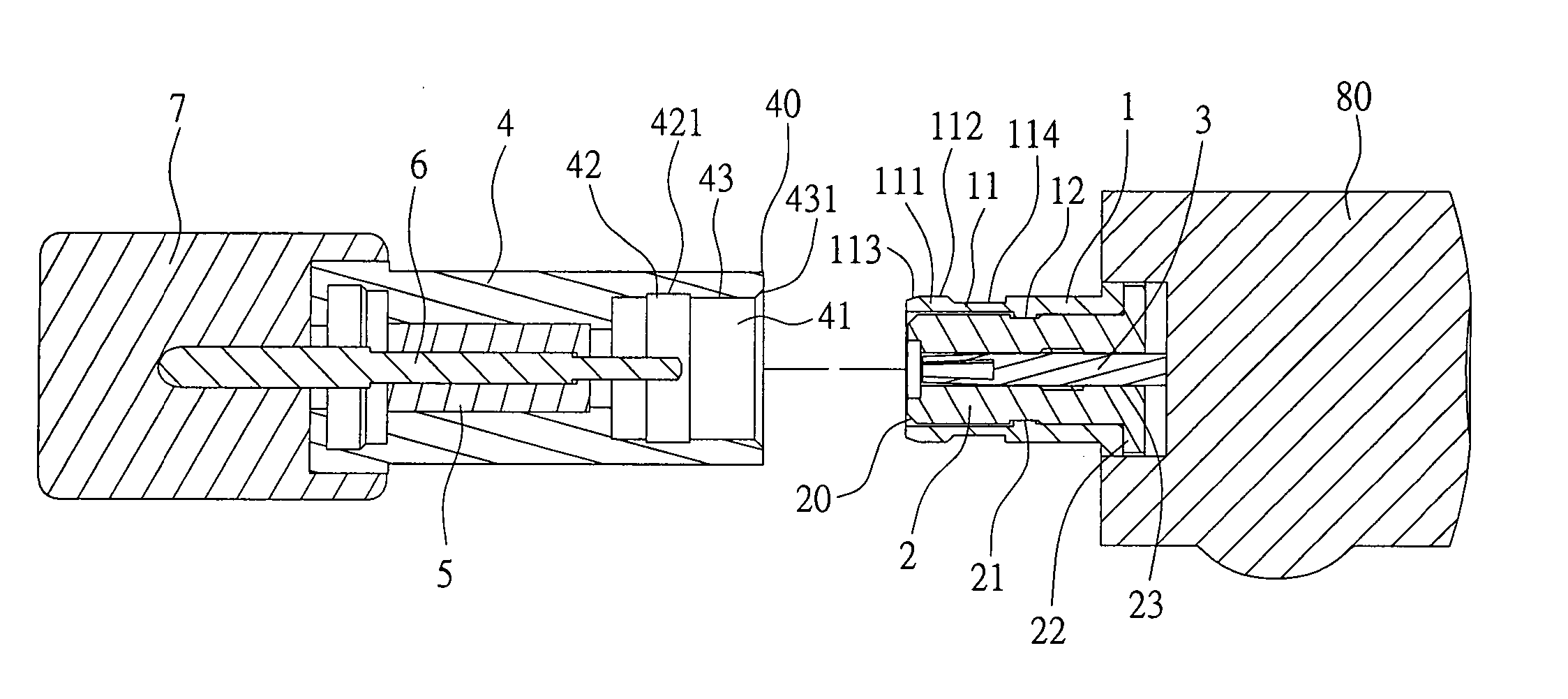
[0008] Through the surface contact of the axial outer ring plane of the spring mechanism to the axial surface groove bottom of the insertion end, the coaxial connector of this invention is stably connected to the mating connector, increasing the torsion force.

Problems solved by technology

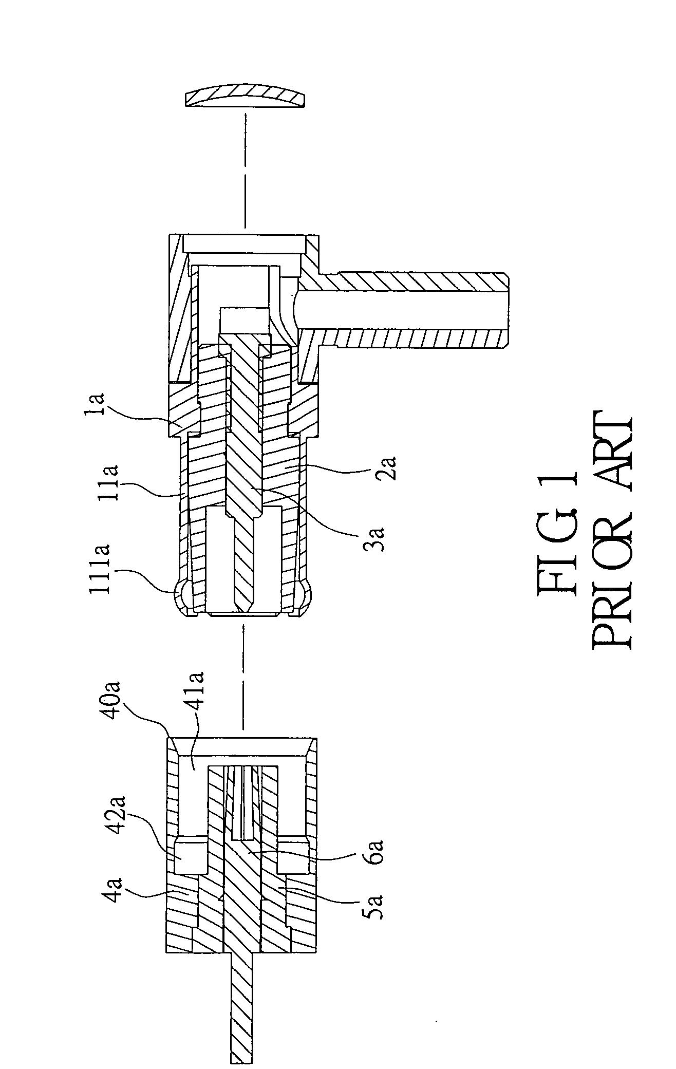
From the conventional coaxial connector described above, the outer convex ring 111a of the elastic fragment 11a is simply connected through threads with a groove bottom of the inner groove 42a of the insertion end 40a, so no sufficiently stable connection to each other occurs, and at the time of rotation of the antenna or the coaxial cable for adjustment, it is difficult to keep the antenna at a desired angle, thereby resulting in a poor articulation of signal received and further degrading the quality of the signal to be transmitted.

Method used


Image

  • Coaxial connector
  • Coaxial connector
  • Coaxial connector

Examples


first embodiment

[0021] Referring now to FIG. 2 to FIG. 4, a first embodiment is provided according to this invention. This invention is a coaxial connector mating with a mating connector, and the coaxial connector comprises a body 1, an insulative sleeve 2, and an electrically conductive terminal 3. The body is an electrically conductive structure, preferably in the form of a cylinder, the front end of the body 1 having a spring mechanism, the free end of the spring mechanism being formed with an outer flange 111, the outer flange 111 having an axial outer ring plane 112. In the embodiment, the spring mechanism is a front end of the body 1 formed with a slit 10 and then with an elastic fragment 11, a free end of each elastic portion 11 being formed with an outer flange 111, the outer flange 111 of each elastic portion 11 being formed with a chamfer 113, an outer ring plane at a fixed end of each elastic fragment 11 being formed with a hook groove 114. An inner surface of the body 1 is formed with a...

second embodiment

[0028] Referring now to FIG. 9, a second embodiment is provided according to this invention. In the embodiment, an extension part is further included, and one end of the extension part 13 is assembled in the back end of the body 1, thereby the entire electrically conductive structure, preferably in the form of a cylinder, is formed.

[0029] Referring now to FIG. 10, a third embodiment is provided according to this invention. In the embodiment, an extension part 14 is further included, and one end of the extension part 14 is assembled in the back end of the body 1, thereby the entire electrically conductive structure, preferably in the form of a cylinder having a bend therein. Apparent from the second embodiment and the third embodiment, the coaxial connector of this invention may form different entire structures according to the connected object required, such as the antenna, the coaxial cable, or the PCB, and also the connected object of the mating connector may match with the coaxia...


PUM


Abstract

This invention is a coaxial connector for mating with a mating connector, an inner surrounding surface of an insertion end of the mating connector being provided with an inner groove having an axial surface groove bottom, the coaxial connector comprising a body having a front end having a spring mechanism, a free end of the spring mechanism being formed with an outer flange with an axial outer ring plane. When the spring mechanism is inserted in an insertion space of the mating connector, the outer flange is inlaid in the inner groove and a surface contact is given on the axial outer ring plane of the outer flange to the axial surface groove bottom of the inner groove. Thereby, the coaxial connector of this invention is stably connected to the mating connector with the increased torsion force to ensure that signals are clearly received and transmitted.

Description

FIELD OF THE INVENTION [0001] The present invention relates to a coaxial connector and particularly to a coaxial connector for improving a torsion force to hold a mating connector. BACKGROUND OF THE INVENTION [0002] As is known, an antenna or a coaxial cable of a product for communication is connected through a coaxial connector to a mating connector connected with a communication module in the communication product for achievement of a signal transmission. In different conditions, users are required to adjust the antenna or an angle of the coaxial cable to get a clear signal. [0003] Referring now to FIG. 1, a conventional coaxial connector is aligned with the mating connector, and the coaxial connector comprises a body 1a, an insulative sleeve 2a, and an electrically conductive terminal 3a. The body 1a is a tubular electrically conductive structure, a front end of the body 1a is provided with a slit (not shown) and formed with an elastic fragment 11a, and a free end of each elastic...

Claims


Application Information

Patent Timeline
IPC IPC(8): H01R13/623H01R12/16H01R9/05H01R13/646
CPCH01R13/623H01R2201/02H01R2103/00H01R24/50
Inventor TSAO, JUNG-TSUNG
Owner MOLEX INC
Learn More