
"Warning Bump" traffic safety device

a technology of traffic safety and warning bumps, which is applied in the direction of traffic signals, instruments, roads, etc., can solve the problems of deficient devices and methods of getting the attention of motorists, complex structures, and the need to anchor devices to the roadway, and achieve the effect of rapid deploymen

Inactive Publication Date: 2005-12-08
SHERMAN TIM +2
View PDF8 Cites 13 Cited by
  • Summary
  • Abstract
  • Description
  • Claims
  • Application Information

AI Technical Summary

Benefits of technology

"The present invention is a traffic safety device that can be used in construction zones or other areas to provide warnings to motorists and individuals. The device is designed to be easily deployed, used in various configurations, and reusable with a long lifespan. It does not adversely affect other traffic control devices or vehicles passing over it. The device incorporates visual and auditory warnings, and can be used in advance-warning areas, transition areas, buffer areas, and work areas. It can also be anchored to roadway surfaces using conventional means. Overall, the invention provides a flexible and effective tool for improving traffic safety."

Problems solved by technology

Many of these various devices and methods of getting the attention of motorists, while effective in some aspects, are deficient in two important ways.
First, they do not provide notice or warning to the workers that a vehicle is approaching or entering the work area or the lateral buffer area and second, they typically engage only the visual sense of the motorists without providing any audible or physical sensation to the approaching motorist.
However, all have significant disadvantages including complexity, the need to anchor the device to the roadway, intricate structures, or lack of means of maintaining the position of the device on the roadway.

Method used


Image

  • "Warning Bump" traffic safety device
  • "Warning Bump" traffic safety device
  • "Warning Bump" traffic safety device

Examples


Embodiment Construction

:

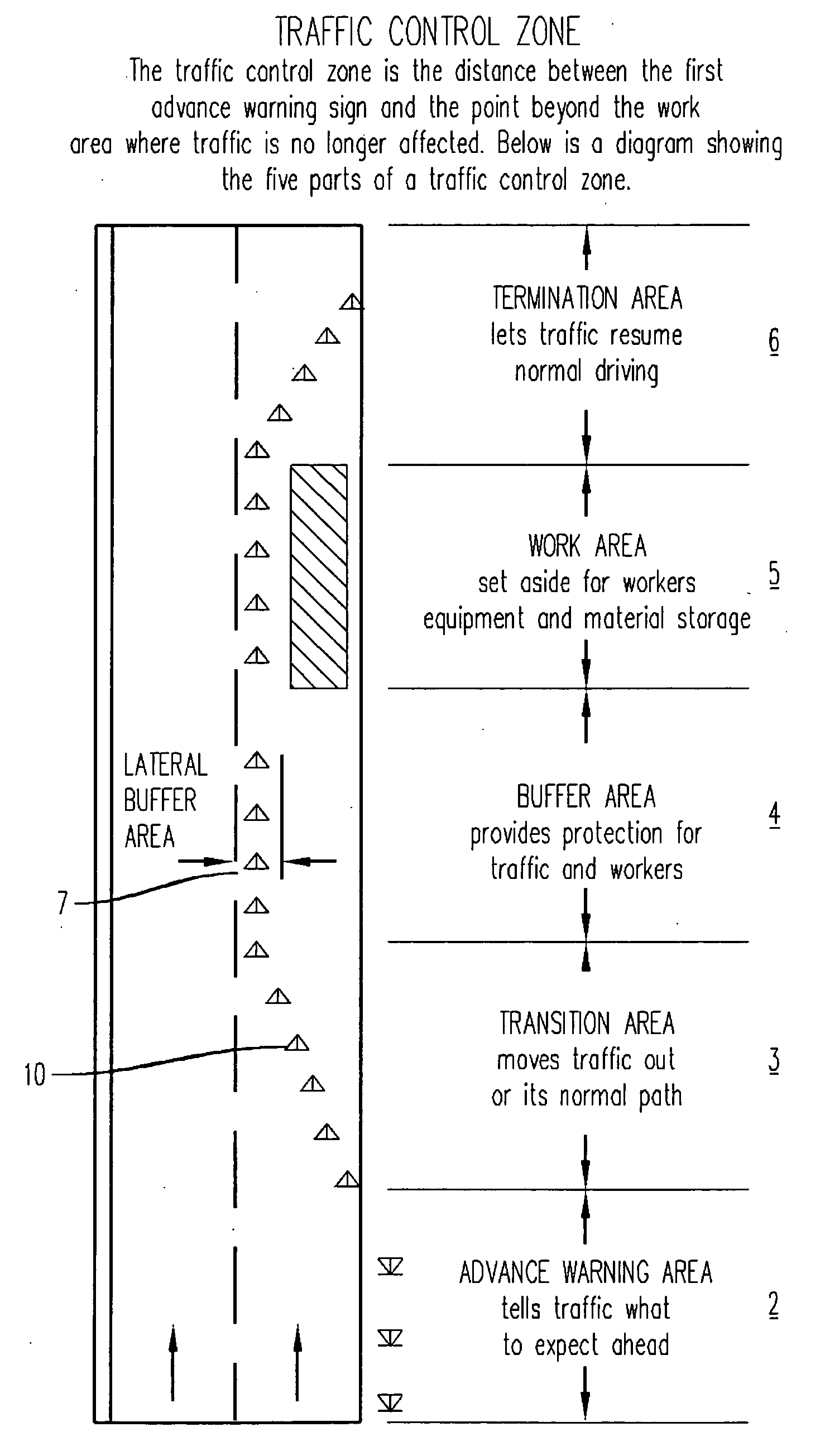
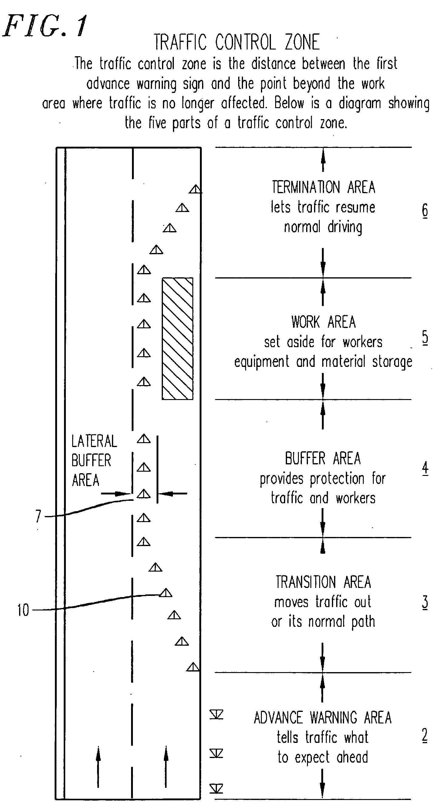
[0043]FIG. 1 describes a typical traffic control zone showing, roadway 1, in which the arrows show the direction of vehicle traffic coming into advanced warning area 2, in which signs and other devices are used to inform drivers of what to expect ahead. Warning area 2 is followed by transition area 3 which contains traffic control devices 10, such as standard barrels or cones, which move the oncoming traffic into a new travel pattern as the traffic approaches buffer area 4, which precedes work area 5, in which actual roadwork occurs. The aforesaid are followed by termination area 6, where the normal traffic pattern is resumed. Traffic control devices 10, located in buffer area 4 are set to create lateral buffer area 7, which provides lateral spacing between work area 5 and the portion of roadway 1 upon which vehicles will traverse the roadway in work area 5.

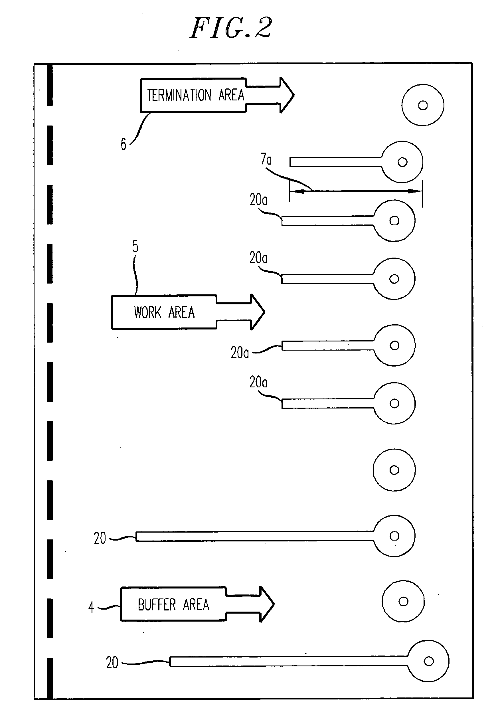
[0044]FIG. 2 depicts the present invention, showing Warning Bumps 20 and 20a, being attached to a plurality of standard traff...


PUM


Abstract

A Warning Bump traffic safety device comprised of a base which is inserted over traffic cones or barrels and a strip and extensions, generally trapezoidal in cross section, attached to the base which extends into the roadway which causes both an audible and sensory warning to motorists driving over these strips. This traffic safety device is typically deployed in construction work zones in the buffer and work areas to provide additional warnings to both drivers as they approach a construction work area and additional warnings to both drivers and construction workers if a driver encroaches into lateral buffer area in the work zone. These traffic safety devices also tend to stabilize the cones and barrels.

Description

I. BACKGROUND OF THE INVENTION: [0001] The field of the invention relates generally to warning devices used to alert motorists entering construction work zones prior to the motorists entering the portion of the roadway on which work is being conducted and devices to warn workers in work zones of encroaching traffic. There are extensive regulations and publications of various government entities describing, in great detail, methods and procedures for setting up safety devices to control traffic in roadway construction projects which are categorized as Traffic Control Zones. These Traffic Control Zones contain several discrete areas with different functions which include: 1) an advance warning area which puts motorists on notice as to what to expect ahead followed by a transition area in which the traffic flow is diverted from its normal path as the vehicles approach the actual work area, 2) a buffer area in which no work is performed and no vehicles or material are stored which provi...

Claims


Application Information

Patent Timeline
Patent Type & Authority Applications(United States)
IPC IPC(8): G08G1/01G08G1/16
CPCG08G1/164E01F9/047E01F9/0122E01F9/688E01F9/654E01F9/529
Inventor SHERMAN, TIMFULAGAR, ROBERT KENNETH JR.PFEIFFER, SCOTT ALLEN
Owner SHERMAN TIM
Learn More