
Receiver for an integrated heterodyne communication system including BAW-type resonators

a communication system and receiver technology, applied in the field of electronic circuits, can solve the problems of not allowing easy integration of the same semiconductor product, much more tricky integration in the semiconductor circuit, etc., and achieve the effect of high performan

Active Publication Date: 2005-12-01
STMICROELECTRONICS SRL
View PDF7 Cites 30 Cited by
  • Summary
  • Abstract
  • Description
  • Claims
  • Application Information

AI Technical Summary

Benefits of technology

[0028] one embodiment of the present invention provides a high performance receiving circuit of a digital communication system which allows full integration within a single semiconductor substrate.

Problems solved by technology

Generally speaking, it is necessary to remove this image frequency which might interfere with the receipt of the RF signal.
In practice, this method and the architecture using such method—which is generally designated by the expression “narrow band architecture” is a delicate task to achieve because of the difficulty of realizing a narrow band filter showing performance.
And much more tricky to integrate in a semiconductor circuit.
These components have the drawback of not allowing easy integration in a same semiconductor product.
The figures mentioned above are a clear obstacle preventing the use of the second method which was discussed before, because of the great difficulty of realizing filters for separating channels providing high selectivity at the radio frequency and, moreover, for providing a complete integration within a same semi-conductor product.

Method used


Image

  • Receiver for an integrated heterodyne communication system including BAW-type resonators
  • Receiver for an integrated heterodyne communication system including BAW-type resonators
  • Receiver for an integrated heterodyne communication system including BAW-type resonators

Examples


first embodiment

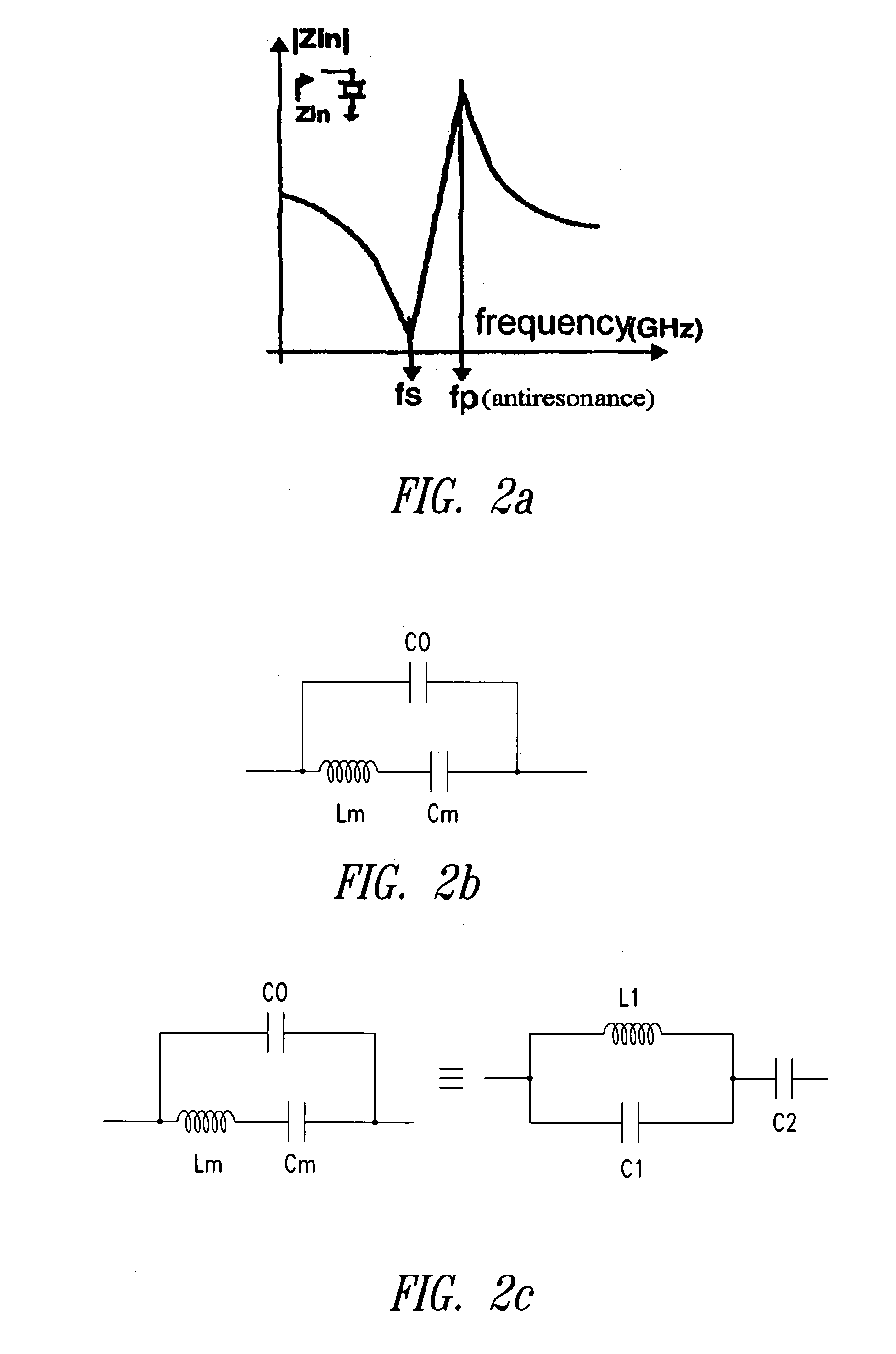
[0076]FIG. 3a illustrates a TRC in which the series resonance of a BAW resonator 212 is acted upon. To this end, an inductor 213 whose inductance is variable so that it can be adjusted in order to start resonating with the parallel capacitance of the resonator (which is close to frequency fp) or in the vicinity of this frequency, is assembled in parallel connection with resonator 212.

[0077] It is then possible to really act on the series resonance and control the resonant frequency by means of a capacitive tuning element 211.

second embodiment

[0078]FIG. 3b corresponds to a TRC in which the parallel resonance of a BAW resonator 222 is now acted upon. To this end, this time an inductor 223 that is variable in order to be adjusted so that it starts resonating with the equivalent series capacitance (C2) close to frequency fs of the resonator of the FIG. 2c, or in the vicinity of this frequency, is connected in series with resonator 222. Then, a capacitive tuning element (221) is connected in parallel with both series elements, to interact with the parallel resonance of resonator 222 and set it to frequency fp.

[0079] Thus, through the combined action of partner elements 221 and 223, it is possible to adjust the operational frequency—within a broad range—by means of tuning element 211 or 221 according to the case.

[0080] Thus, there is a true co-operation between tuning element 211 (or 221) and inductor 213 (resp. 223) that, by its action in the vicinity of both resonant and anti-resonant frequencies of the acoustic resonator,...


PUM


Abstract

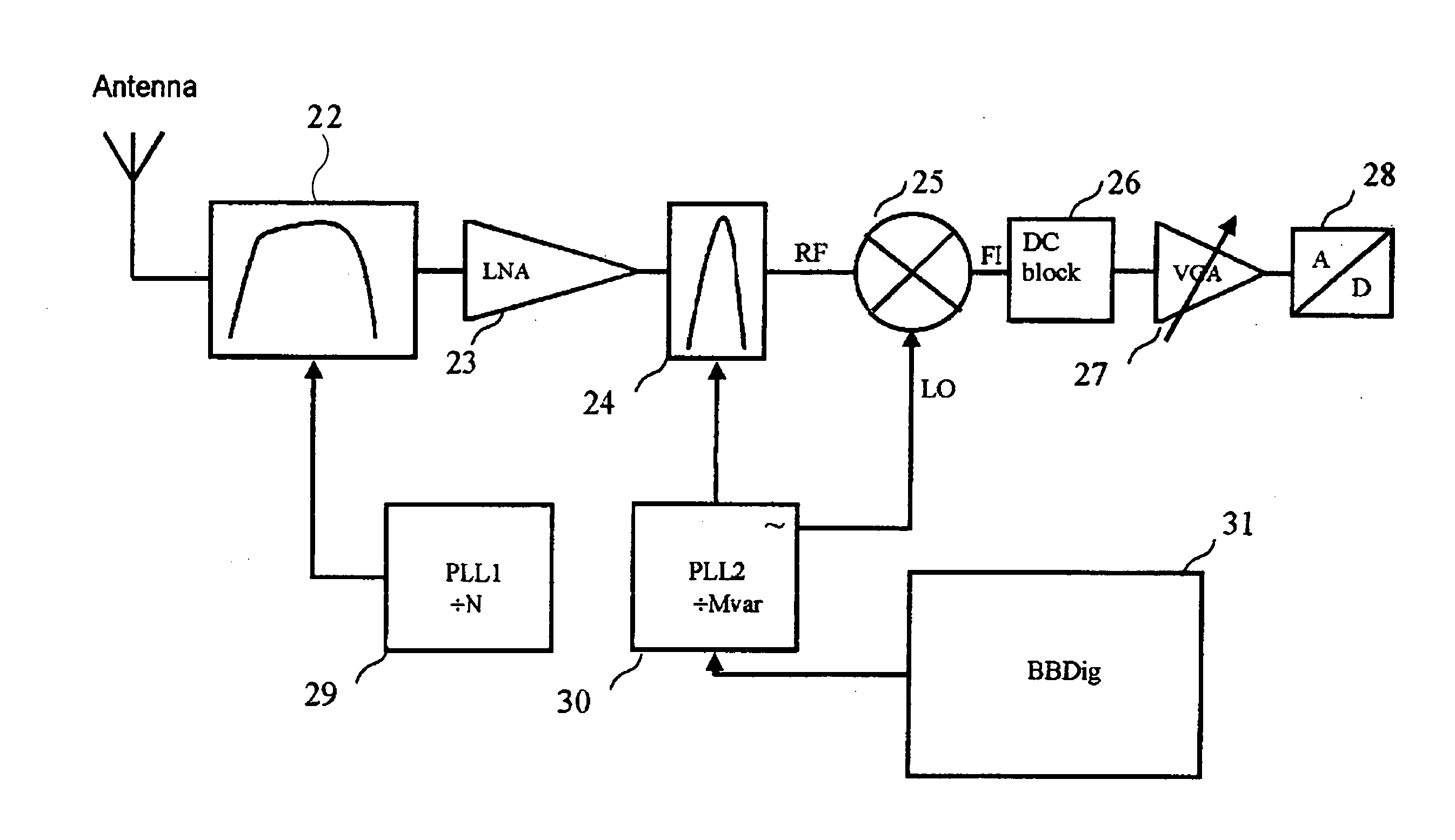
A heterodyne receiving circuit for a digital communication system including a first band pass filter receiving a signal from an antenna, an amplifying circuit and a second narrow band pass filter for selecting one particular channel within a band of frequencies. The two filters are carried out with integrated BAW-type tunable resonators which can be adjusted, respectively, by a first electrical signal and a second electrical signal generated by two PLL-type frequency control loops. The second frequency control loop has a variable division factor for the purpose of selecting one particular channel within said band of frequencies. In addition, the receiving circuit includes a mixer for mixing the signal generated at the output of said second filter with a local oscillation frequency in order to produce an intermediate frequency. The division factor is controlled by a digital processing of the intermediate frequency.

Description

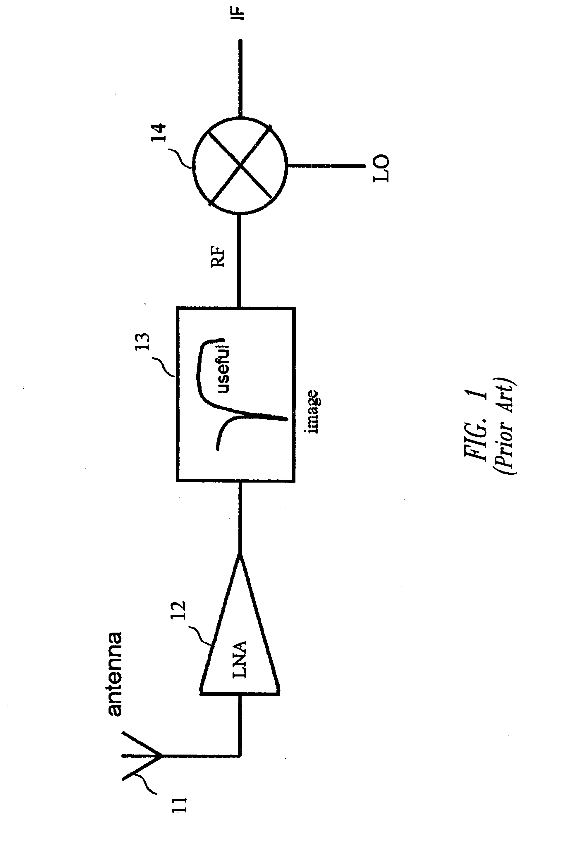
BACKGROUND OF THE INVENTION [0001] 1. Field of the Invention [0002] The present invention relates to the field of electronic circuits used in data transmission, and more particularly a receiver for an integrated heterodyne communication system including BAW type resonators. [0003] 2. Description of the Related Art [0004] The heterodyne architecture was developed in the beginning of the XXth century for the purpose of improving wireless communication. Such architecture is still used in the more recent mobile receivers: mobile telephones, so-called pagers, 433 Mhz receivers etc . . . . [0005] The principle of the heterodyne architecture is shown in FIG. 1, where a low noise amplifier 12 receives a Radio Frequency (RF) signal generated by an antenna 11 and operating at a frequency fRF. A filtering element 13 is inserted between amplifier 12 and a frequency mixer 14. The frequency mixer brings back the RF signal to another frequency which is generally designated by the expression Interm...

Claims


Application Information

Patent Timeline
Patent Type & Authority Applications(United States)
IPC IPC(8): H03H7/01H03H9/74H04B1/10H04B1/26H04B1/28
CPCH03H7/0169H03H9/74H04B1/28
Inventor CATHELIN, ANDREIABELOT, DIDIER
Owner STMICROELECTRONICS SRL
Learn More