
Display apparatus displaying three-dimensional image and display method for displaying three-dimensional image

Inactive Publication Date: 2005-12-01
KK TOSHIBA
View PDF8 Cites 31 Cited by
  • Summary
  • Abstract
  • Description
  • Claims
  • Application Information

AI Technical Summary

Benefits of technology

[0028] It is an object of the present invention to provide a three-dimensional display apparatus that can improve resolution.

Problems solved by technology

However, it is difficult for an orthographic-projection three-dimensional display apparatus (II system) comprising lenticular lenses or slits to provide fine character expressions or smooth curve displays owing to a limit to the resolution, determined by the pitch of the lenticular lenses or slits.
If a three-dimensional image having a depth is to be displayed, then disadvantageously, anti-aliasing may make the boundary between a background and an image notched, or in a near-side region (a space in front of the apparatus and close to the observer), the observer may see a double image near an near-side limit of 3D image position.
This is because crosstalk causes the observer to see not only a parallax image to be originally viewed but also an adjacent parallax image, thus preventing the observer from seeing only the correct parallax image.
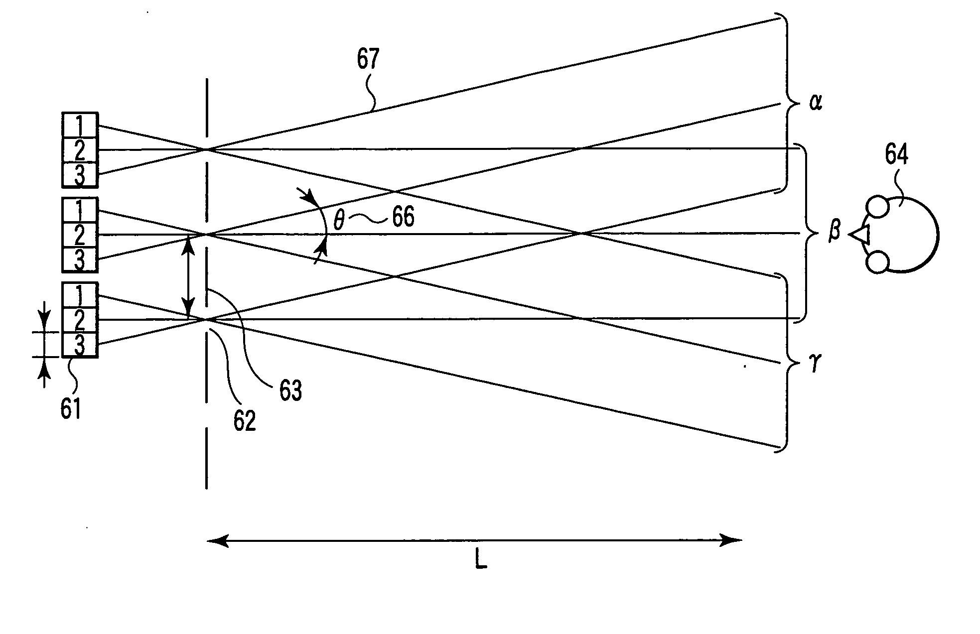
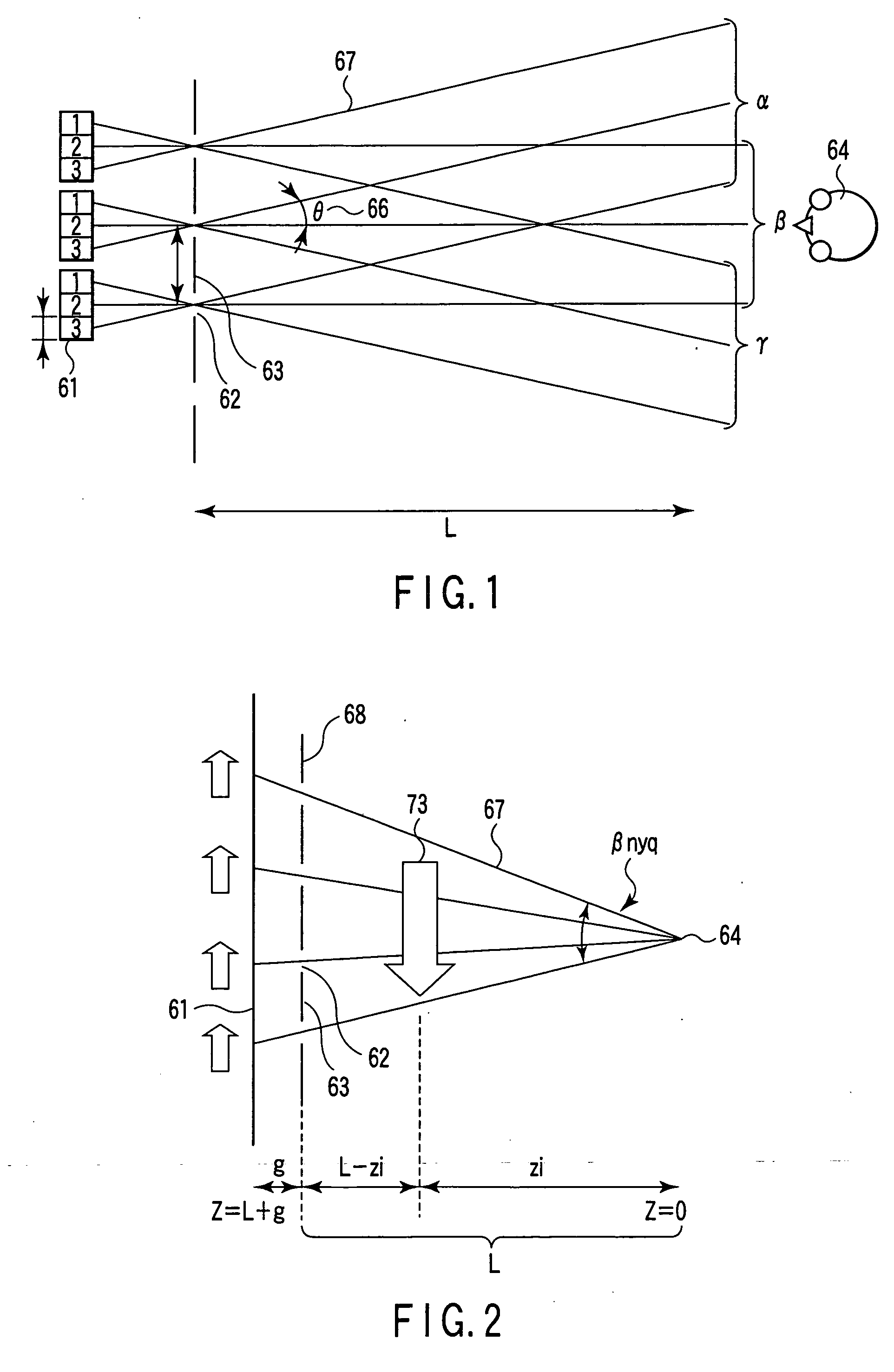
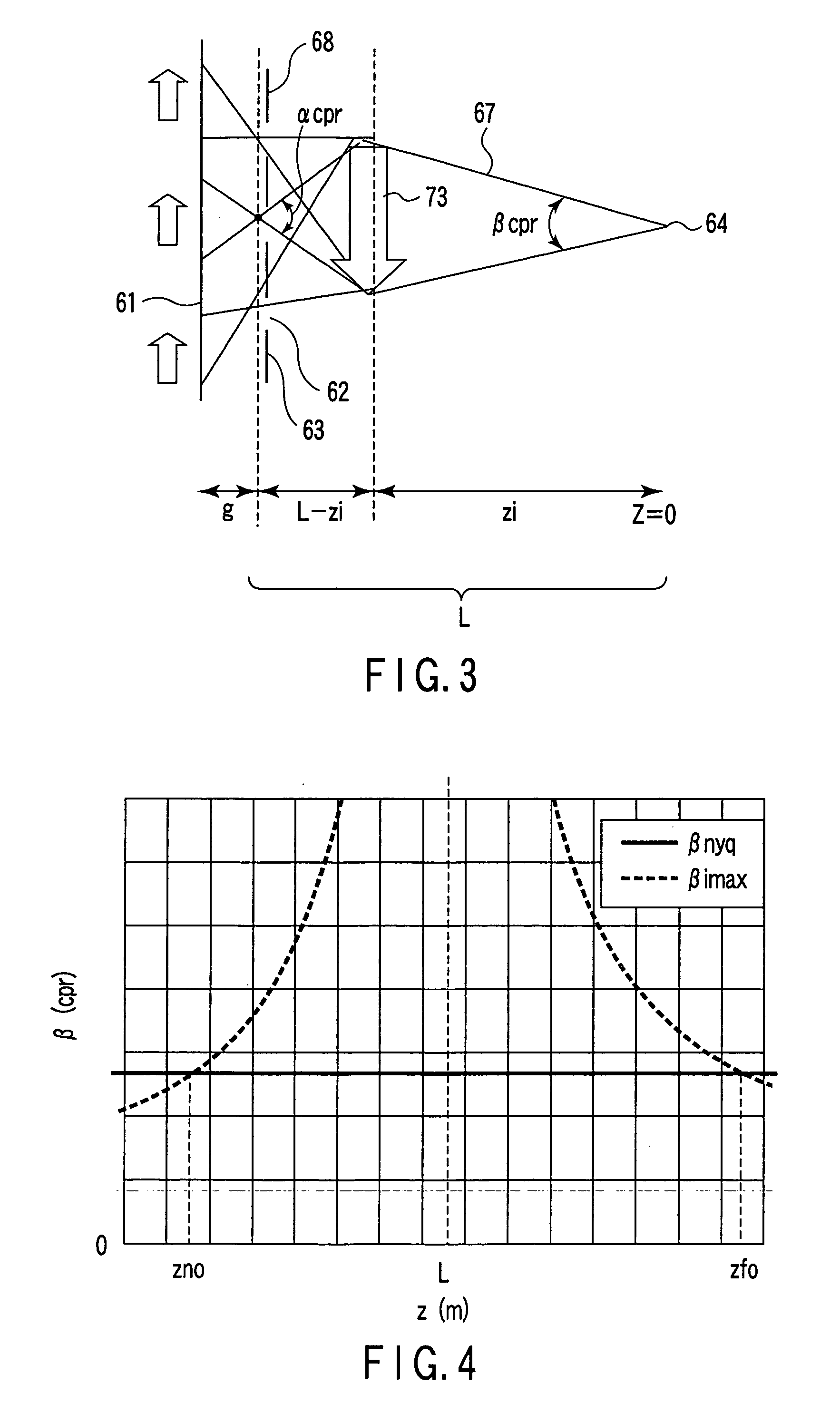
A problem with the II system is that when a three-dimensional image is reproduced at a position away from the display surface, a pencil of light rays assigned via the apertures or lenses spread to rapidly reduce the resolution.
Accordingly, this cannot be easily realized.
If for example, a round ball is to be displayed in a far-side direction, the contour of the round ball may disadvantageously be notched.
The crosstalk may reduce the resolution.

Method used


Image

  • Display apparatus displaying three-dimensional image and display method for displaying three-dimensional image
  • Display apparatus displaying three-dimensional image and display method for displaying three-dimensional image
  • Display apparatus displaying three-dimensional image and display method for displaying three-dimensional image

Examples


Embodiment Construction

[0069] With reference to the drawings, a detailed description will be given of a display apparatus according to embodiments of the present invention.

[0070]FIG. 5 is a horizontal sectional view schematically showing a three-dimensional display apparatus according to a first embodiment of the present invention. As shown in FIG. 5, lenticular lenses 2 as ray control elements are arranged in front of a display surface of a two-dimensional display module 1 via a gap g. Pixels are arranged on the two-dimensional display module 1 at a pixel pitch Pp. The lenticular lenses 3 are arranged in a horizontal direction at a lens pitch lp with the major axis of each lenticular lens 2 extending in a vertical direction. Each lenticular lens 2 has a focal distance f. The display apparatus shown in FIG. 5 is also provided with a gap varying section 4; a specific example of the structure of the gap varying section 4 will be described later. The gap varying section 4 adjusts the gap in accordance with ...


PUM


Abstract

A three-dimensional display apparatus is provided with an optical element including optical apertures arranged opposite a display module and in association with the parallax images. The optical apertures cause the parallax images to be displayed in a near-side region closer to an observer, while causing a three-dimensional image to be displayed in a far-side region located opposite the observer with respect to the display module. When a smooth three-dimensional image is to be displayed in the near-side region, the optical gap between the optical element and the display surface is set longer than a reference distance depending on the position of the three-dimensional image. In order to display a smooth three-dimensional image in the far-side region, the observer sets the optical gap shorter than the reference distance depending on the position of the three-dimensional image.

Description

CROSS-REFERENCE TO RELATED APPLICATIONS [0001] This application is based upon and claims the benefit of priority from prior Japanese Patent Application No. 2004-153742, filed May 24, 2004, the entire contents of which are incorporated herein by reference.BACKGROUND OF THE INVENTION [0002] 1. Field of the Invention [0003] The present invention relates to a display apparatus displaying a three-dimensional image and a display method of displaying a three-dimensional image, and in particular, to a display apparatus displaying a three-dimensional image which apparatus comprises an optical plate, i.e., a ray control element controlling a direction in which light rays are applied, as well as a display method of displaying a three-dimensional image. [0004] 2. Description of the Related Art [0005] An integral imaging method (also simply referred to as an II system below) for displaying a large number of parallax images is known as a system for recording a three-dimensional image and reproduc...

Claims


Application Information

Patent Timeline
IPC IPC(8): H04N13/04G02B30/27H04N13/00
CPCH04N13/0404G02B27/2214H04N13/305G02B30/27
Inventor TAKAGI, AYAKOSAISHU, TATSUOTAIRA, KAZUKIHIRAYAMA, YUZO
Owner KK TOSHIBA
Learn More