
Image display system, image display method and display unit

a technology of image display system and image display method, applied in the field of image display system, can solve problems such as the tendency of complex operation of the remote controller

Active Publication Date: 2005-11-24
SATURN LICENSING LLC
View PDF9 Cites 149 Cited by
  • Summary
  • Abstract
  • Description
  • Claims
  • Application Information

AI Technical Summary

Benefits of technology

[0012] It is another object of the present invention to provide a picture display system and a picture display method in which, in supplying picture signals from the base device to two or more display devices, the base device may be remote-operated from one display device to enable pictures to be displayed on the other display device, through the use of the above-described bidirectional communication system, and a display device in such image display system in which it is possible to remote-operate the base device.

Problems solved by technology

However, with the system in which, for having the TV receiver, STB or the IRD perform the targeted operations, the needed information, such as menu or guidance, is demonstrated on the display image surface, and a remote controller is actuated, as the user views the so displayed information, the remote controller operation tends to be complicated.

Method used


Image

  • Image display system, image display method and display unit
  • Image display system, image display method and display unit
  • Image display system, image display method and display unit

Examples


Embodiment Construction

[0043] A picture display system according to the present invention and a picture display system and apparatus used in this picture display system are hereinafter explained in detail with reference to the drawings.

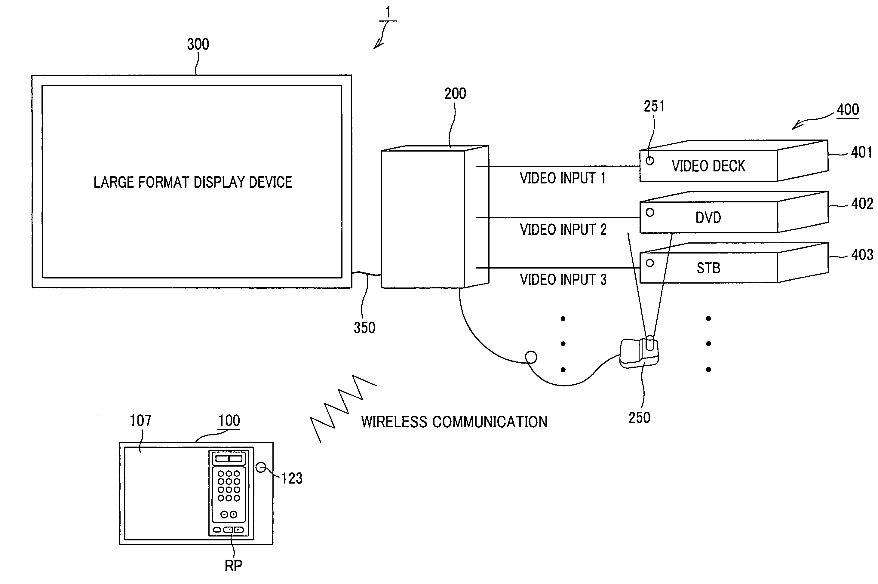
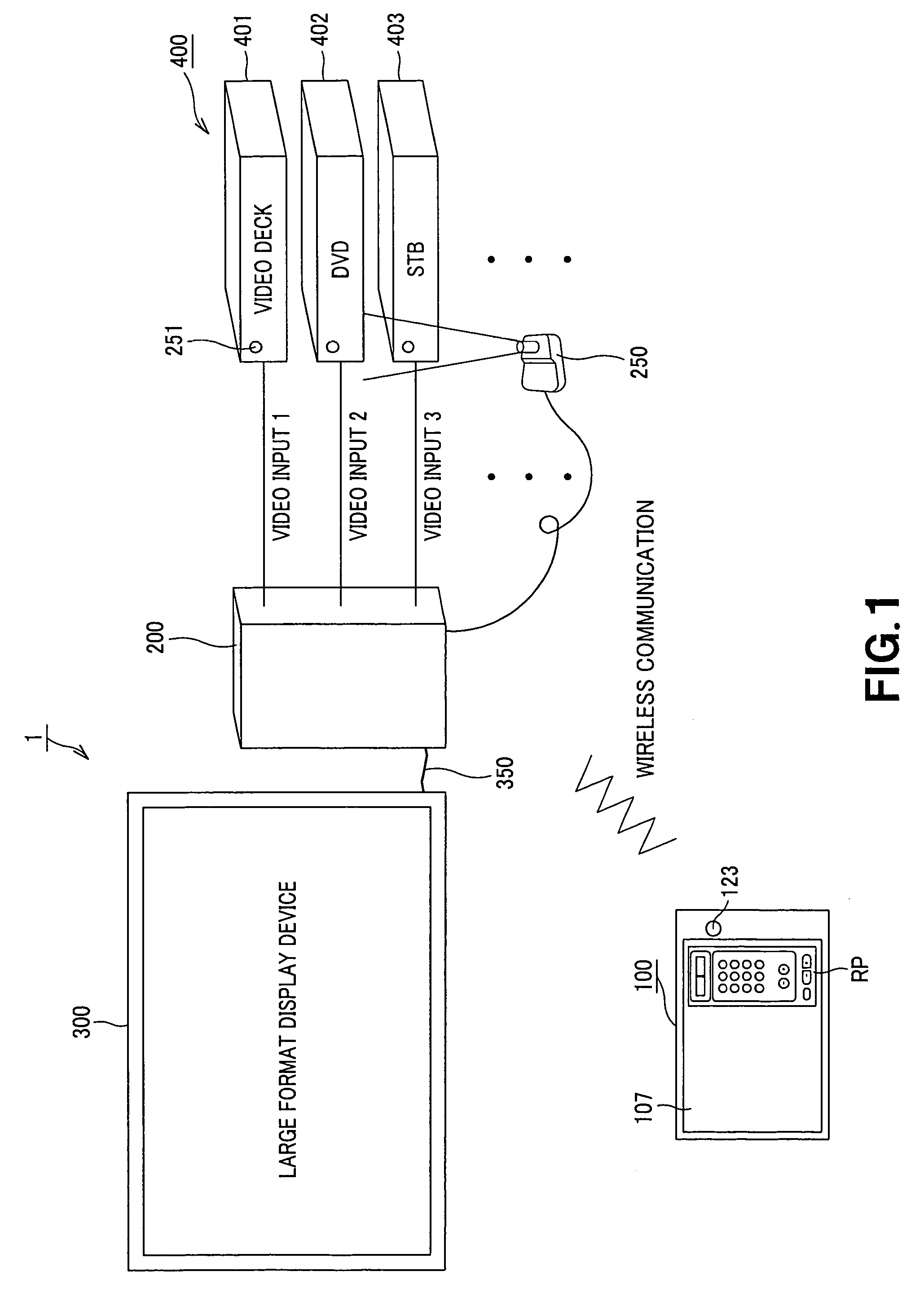
[0044] In the following example, the present invention is applied to a picture display system having a large format display device (first display device), a mobile display device (second display device) and a base device (base station) for supplying pictures at least to this large format display device. The base device is remote-controlled by wireless communication by the mobile display device to control the external input device supplying a picture to the large format display device to effect wireless bidirectional communication between the base device and the mobile display device adapted for displaying a picture on the large format display device.

[0045]FIG. 1 schematically shows a picture display system according to the present invention. Referring to FIG. 1, the pictu...


PUM


Abstract

A picture display system having two display devices and a base device for supplying picture signals to one of the display devices and capable of having bidirectional communication with the other display device is disclosed. The picture display system (1) is made up by a mobile display device (100), a base device (200) and a large format display device (300). The base device (200) sends picture signals to the display device (100) and to the large format display device (300). On a display image surface of the mobile display device (100), there is provided a touch panel for detecting the contact position contacted by a user for displaying a remote-control panel RP accepting an operating input from the user on the display image surface. An operating signal conforming to a display item of the remote-control panel RP, displayed at a contact position, detected by the touch panel, is generated and transmitted by wireless communication to the base device (200). This base device (200) selects the picture signals, supplied from the external inputting devices (400), as a supply source of picture signals, responsive to an operating signal, to transmit the so selected picture signals to the large format display device (300).

Description

TECHNICAL FIELD [0001] This invention relates to a picture display system having two display devices and a base device for supplying picture signals to one of the display devices and capable of having bidirectional communication with the other display device. This invention also relates to a picture display method for the picture display system, and to a display apparatus used in this picture display system and capable of having bidirectional communication with the base device. [0002] This application claims priority of Japanese Patent Application No. 2002-197683, filed in Japan on Jul. 5, 2002, the entirety of which is incorporated by reference herein. BACKGROUND ART [0003] In adjusting the picture quality or setting the timer in e.g. a TV receiver, a menu for selecting the processing that may be executed is displayed on a display image surface of a TV receiver by e.g. button actuation of a remote controller of the TV receiver. A user selects the targeted processing, using the remo...

Claims


Application Information

Patent Timeline
IPC IPC(8): G06F3/048G09G5/00H04N5/00H04N5/38H04N5/44H04N5/445
CPCH04N5/38H04N2005/4441H04N7/163H04N21/4122H04N21/4126H04N21/4316H04N21/43637H04N21/47H04N21/485H04N2005/4407H04N2005/441H04N2005/4414H04N2005/4419H04N2005/4423H04N2005/443H04N5/4403H04N21/42209H04N21/478H04N21/42214H04N21/42224H04N21/42228H04N21/42204H04N21/41265H04N21/42208
Inventor UCHIDA, MAMIYOKOYAMA, TATSUYAOHASHI, YUKAMIZOBUCHI, AYUMISATO, JINSAYAMA, YUSHI
Owner SATURN LICENSING LLC
Learn More