
Supporting unit for liquid crystal display apparatus, backlight assembly and liquid crystal display apparatus having the same

a technology of liquid crystal display and backlight assembly, which is applied in the direction of static indicating devices, instruments, non-linear optics, etc., can solve problems such as deteriorating image display quality, and achieve the effect of improving image display quality

Inactive Publication Date: 2005-11-24
SAMSUNG ELECTRONICS CO LTD
View PDF3 Cites 48 Cited by
  • Summary
  • Abstract
  • Description
  • Claims
  • Application Information

AI Technical Summary

Benefits of technology

[0009] The present invention provides a supporting unit for an LCD panel, which is capable of preventing pollution of a display region, a backlight assembly having the supporting unit and an LCD apparatus having the supporting unit.
[0012] The supporting unit in accordance with an exemplary embodiment of the present invention includes a first support frame, a second support frame and an impurity barrier. The first support frame supports a liquid crystal display panel, and includes an opening through which a light is supplied to the liquid crystal display panel. The second support frame is protruded from sides of the first support frame to surround sides of the liquid crystal display panel. The impurity barrier is disposed on a surface of the first support frame corresponding to the liquid crystal display panel to prevent an inflow of impurities into a space between the first support frame and the liquid crystal display panel.
[0015] The liquid crystal display apparatus in accordance with an exemplary embodiment of the present invention includes a first receiving container, a lamp unit, a liquid crystal display panel, a supporting unit, a second receiving container and a chassis. The first receiving container includes a first bottom surface and a plurality of first sidewalls disposed on sides of the first bottom surface to form a receiving space. The lamp unit is disposed in the receiving space to generate a light. The liquid crystal display panel transforms the light into an image light. The supporting unit includes a first support frame, a second support frame and an impurity barrier. The first support frame has an opening through which the light is supplied to the liquid crystal display panel, and supports the liquid crystal display panel. The second support frame is protruded from sides of the first support frame to surround sides of the liquid crystal display panel. The impurity barrier is disposed on a surface of the first support frame corresponding to the liquid crystal display panel to prevent an inflow of impurities into a space between the first support frame and the liquid crystal display panel. The second receiving container includes a second bottom surface and a plurality of second sidewalls disposed on sides of the second bottom surface to surround the first sidewalls of the first receiving container. The chassis includes a top chassis wall and a plurality of side chassis walls that surrounds the liquid crystal display panel. A central portion of the top chassis wall is opened to expose a central portion of the liquid crystal display panel.
[0017] Therefore, the supporting unit for the LCD panel includes the impurity barrier to prevent the inflow of the impurities that is externally provided into the space between the supporting unit and the LCD panel, thereby improving image display quality.

Problems solved by technology

The LCD apparatus, however, is operated in an atmosphere that is exposed by the impurities such as dusts, particles, liquid pollutants, etc., so that the LCD apparatus may be polluted, thereby deteriorating image display quality.

Method used


Image

  • Supporting unit for liquid crystal display apparatus, backlight assembly and liquid crystal display apparatus having the same
  • Supporting unit for liquid crystal display apparatus, backlight assembly and liquid crystal display apparatus having the same
  • Supporting unit for liquid crystal display apparatus, backlight assembly and liquid crystal display apparatus having the same

Examples


Embodiment Construction

[0045] Hereinafter, the present invention will be described in detail with reference to the accompanying drawings.

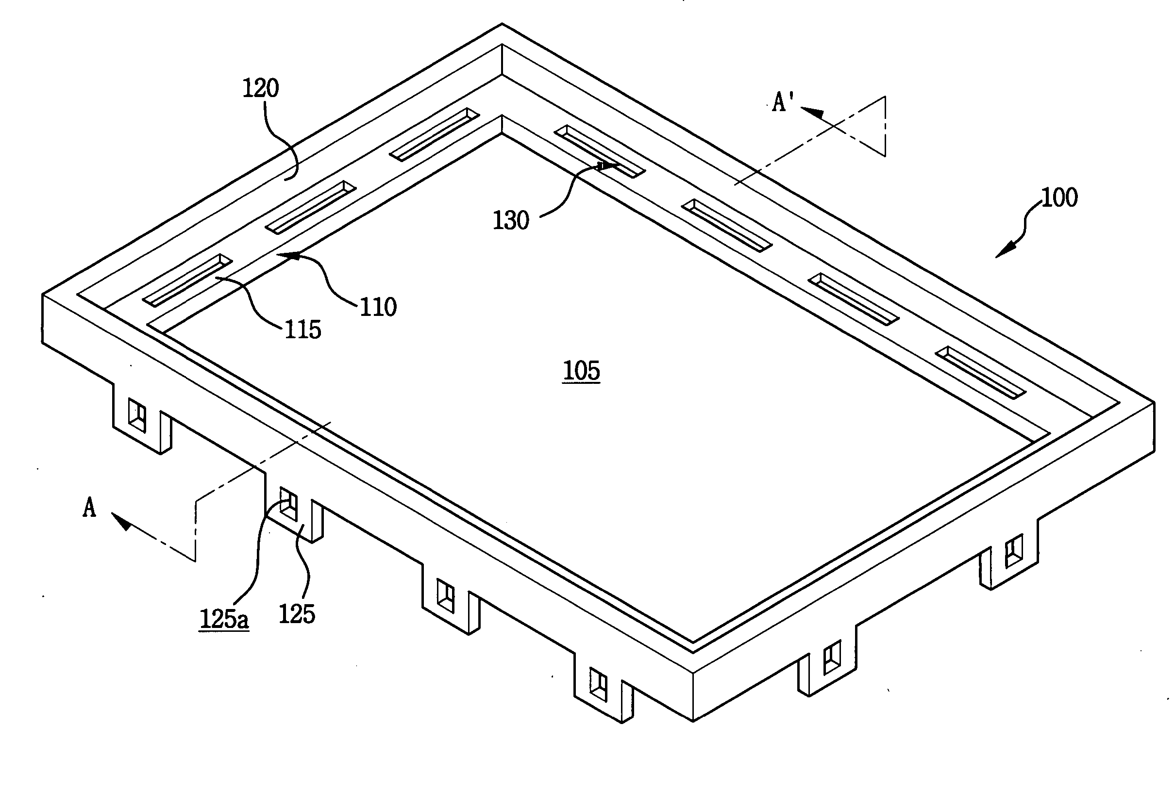
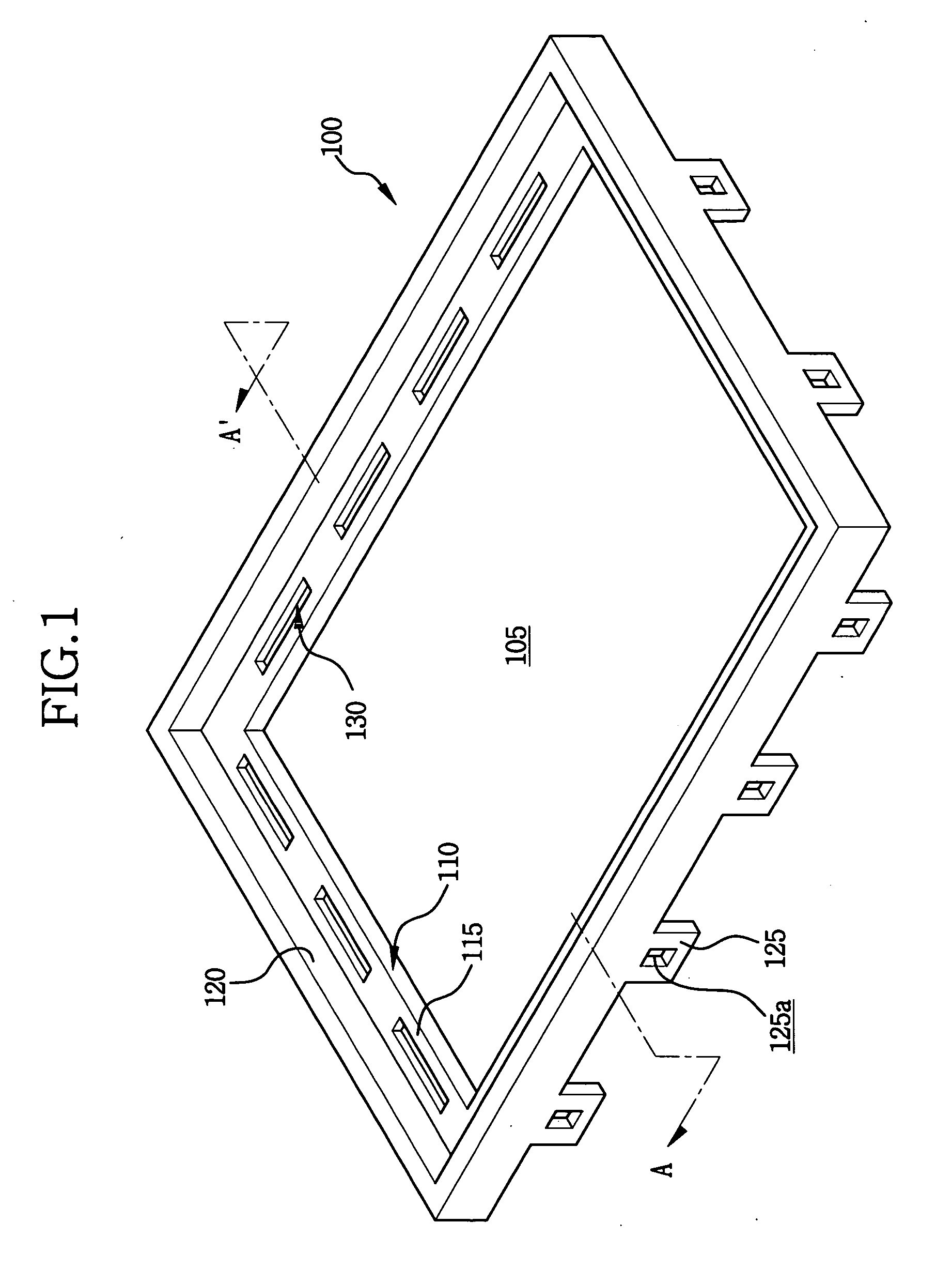
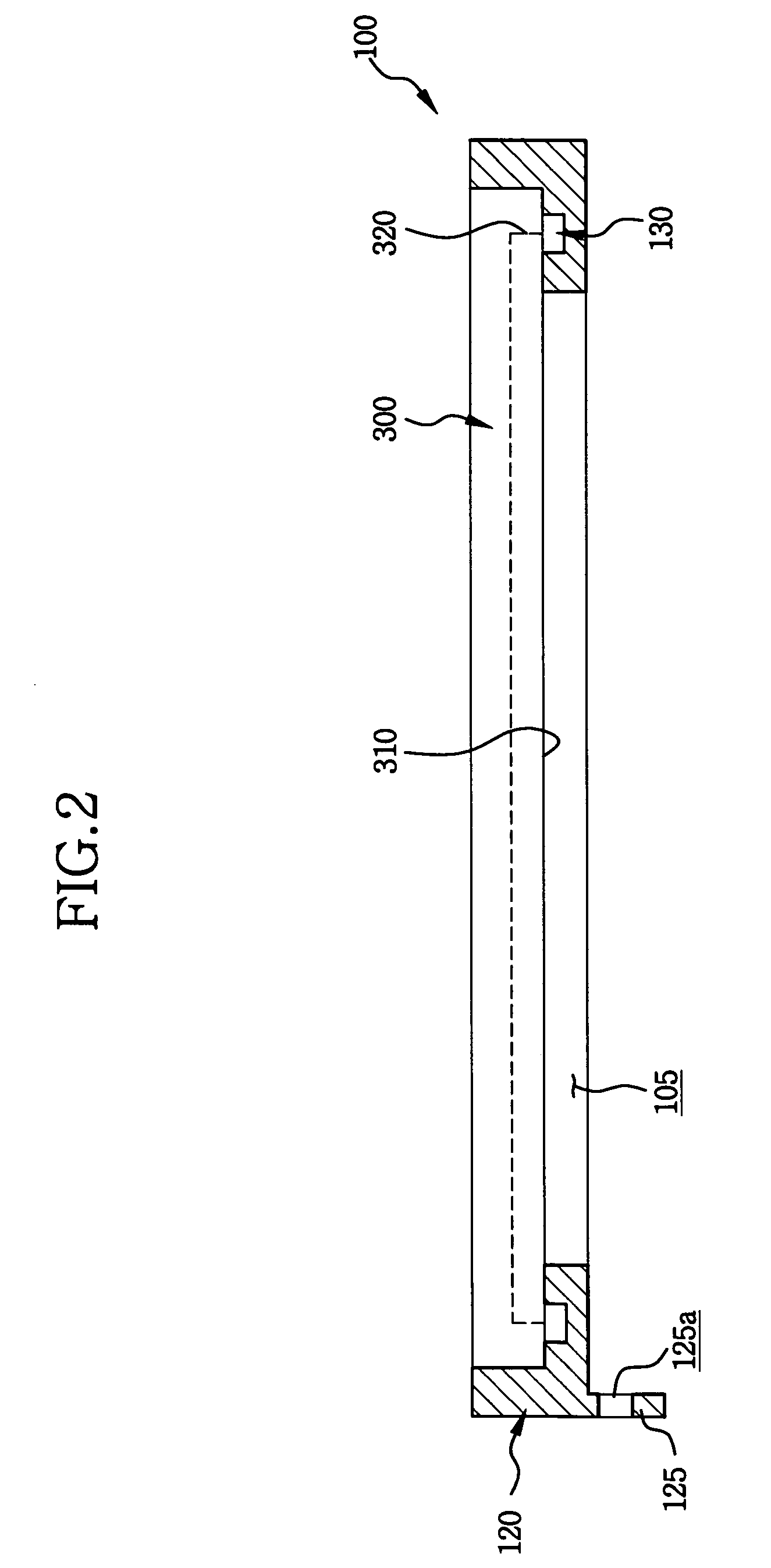
[0046]FIG. 1 is a perspective view showing a supporting unit for an LCD panel according to an exemplary embodiment. FIG. 2 is a cross-sectional view taken along a line A-A′ shown in FIG. 1.

[0047] Referring to FIGS. 1 and 2, the supporting unit 100 for the liquid crystal display (LCD) panel 300 supports the LCD panel 300. The supporting unit 100 has a rectangular shape including an opening 105 formed on a central portion of the supporting unit 100.

[0048] The supporting unit 100 includes a first support frame 110, a second support frame 120 and an impurity barrier 130.

[0049] The first support frame 110 supports a bottom surface 310 of the LCD panel 300. A first surface 115 of the first support frame 110 makes contact with sides of the bottom surface 310 of the LCD panel 300. The bottom surface 310 of the LCD panel 300 has a rectangular shape, and the first support fram...


PUM


Abstract

A supporting unit includes a first support frame, a second support frame and an impurity barrier. The first support frame supports an LCD panel, and includes an opening through which a light is supplied to the LCD panel. The second support frame is protruded from sides of the first support frame to surround sides of the LCD panel. The impurity barrier is disposed on a surface of the first support frame corresponding to the liquid crystal display panel to prevent an inflow of impurities into a space between the first support frame and the liquid crystal display panel. Therefore, the supporting unit for the LCD panel includes the impurity barrier to prevent the inflow of the impurities that is externally provided into the space between the supporting unit and the LCD panel, thereby improving image display quality.

Description

BACKGROUND OF THE INVENTION [0001] 1. Field of the Invention [0002] The present invention relates to a supporting unit for a liquid crystal display (LCD) panel, a backlight assembly having the supporting unit and an LCD apparatus having the supporting unit. More particularly, the present invention relates to a supporting unit for an LCD panel, which is capable of preventing pollution of a display region, a backlight assembly having the supporting unit and an LCD apparatus having the supporting unit. [0003] 2. Description of the Related Art [0004] A liquid crystal display (LCD) apparatus displays an image using a liquid crystal. [0005] The LCD apparatus includes a light generating unit and a liquid crystal controlling unit. A receiving container receives the light generating unit and the liquid crystal controlling unit. [0006] Impurities disposed between the light generating unit and the liquid crystal controlling unit block a light to deteriorate display quality of an image. [0007] ...

Claims


Application Information

Patent Timeline
IPC IPC(8): G02F1/13G02F1/1333G09G3/36
CPCG02F1/133308G02F2201/465G02F2001/133317G02F2001/133311G02F1/133311G02F1/133317
Inventor PARK, JONG-DAELEE, SEOK-WONLEE, TAE-JIN
Owner SAMSUNG ELECTRONICS CO LTD
Learn More