
Backlight device and flat display device using same

A technology of backlight source and point light source, applied in the field of side light type backlight source device, can solve the problems of reducing the luminous efficiency and life of LED101, reducing the contact area, and not fully diffusing LED101, etc. The effect of image display quality and long life

Inactive Publication Date: 2011-05-11
SHARP KK
View PDF1 Cites 28 Cited by
  • Summary
  • Abstract
  • Description
  • Claims
  • Application Information

AI Technical Summary

Problems solved by technology

However, in this case, due to the flexibility of the FPC 102, the circuit board may be warped in a high-temperature environment and the contact area with the heat sink 103a may be reduced.
When the contact area between the FPC102 and the cooling plate 103a becomes small, the heat emitted by the LED101 cannot be sufficiently diffused, which may lead to a reduction in the luminous efficiency and life of the LED101.

Method used


Image

  • Backlight device and flat display device using same
  • Backlight device and flat display device using same
  • Backlight device and flat display device using same

Examples


Embodiment Construction

[0032] Embodiments of a backlight device and a flat-panel display device using the same according to the present invention will be described below with reference to the drawings. In addition, a liquid crystal display device using a liquid crystal in a display panel will be described below as an example of a flat display device.

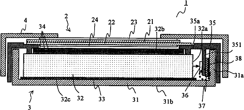
[0033] figure 1 It is a schematic cross-sectional view showing the structure of the liquid crystal display device of the present embodiment. A liquid crystal display device 1 of the present embodiment includes a liquid crystal panel 2 and a backlight unit 3 .

[0034] The liquid crystal panel 2 is formed by sealing liquid crystal (not shown) between a pair of glass substrates 21 and 22 facing apart. The outer edge of the glass substrate 22 extends further outside the glass substrate 21 , and a plurality of electrode terminals (not shown) for applying voltage to pixel electrodes formed on the surface of the glass substrate 22 are formed on the exten...


PUM


Abstract

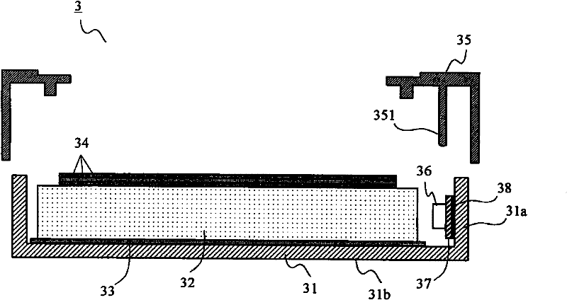
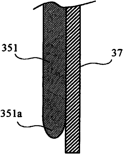
A backlight device (3) is equipped with a light guide plate (32), a chassis (31) whereon the light guide plate (32) is mounted, a frame (35) that grips the light guide plate (32) in conjunction with the chassis (31), a spot light source (36) provided near the side face of the light guide plate (32), a flexible printed circuit board (37) whereon the spot light source (36) is mounted, and a heat-dissipation plate (31a) (a part of the chassis (31)) adhered to the flexible printed circuit board (37) by means of a two-sided adhesive (38). A projecting part (351) is provided in contact with the flexible printed circuit board (37) on the frame (35) to press the flexible printed circuit board (37) toward the heat-dissipation plate (31a), and the tip of the projecting part (351) is tapered toward the end and is away from the flexible printed board (37).

Description

technical field [0001] The present invention relates to a backlight device used to illuminate a display panel from the back, and more specifically, to an edge-light type backlight device using point light sources. In addition, it relates to a flat display device using such a backlight device. Background technique [0002] In a display device such as a liquid crystal display device in which the display panel itself does not emit light, a so-called backlight device that illuminates the display panel from the back is generally arranged. In this backlight device, there are direct type, side light type, planar light type, etc., and the side light type is widely used as display devices become thinner and lighter. [0003] In this edge-light type backlight device, the light source is arranged near the side surface of the light guide plate, and the light emitted from the light source enters the light guide plate from the side surface of the light guide plate. The light incident on...

Claims


Application Information

Patent Timeline
Patent Type & Authority Applications(China)
IPC IPC(8): F21S2/00F21V29/00G02F1/1333G02F1/13357F21Y101/02
CPCG02B6/0068G02B6/0083G02B6/0085G02B6/0088G02F1/133308G02F1/133317G02F1/133322
Inventor 滨田哲也
Owner SHARP KK
Learn More