Method and system for measuring attributes on a three-dimenslonal object

a technology of three dimensions and attributes, applied in the direction of organ movement/change detection, digital computer details, amplifier modifications to reduce noise influence, etc., can solve the problems of restricting the measurement of all sides of the object of interest, affecting the accuracy of the system, and generally affecting the sight of the air

Inactive Publication Date: 2005-11-17
CONCEPTUAL ASSETAB
View PDF15 Cites 18 Cited by
  • Summary
  • Abstract
  • Description
  • Claims
  • Application Information

AI Technical Summary

Benefits of technology

[0025] mitigating any local surface distortion from the probe's contact force on soft material,

Problems solved by technology

One limitation of the above system in measuring many points on an object is that the object must remain in a fixed location and orientation during the measurement session.
Another limitation of a sonic system is that temperature variations (and to a lesser extent humidity and pressure) greatly influence the accuracy of the system.
A further limitation of the optical systems is that maintaining “line-of-sight” through the air is generally problematic.
This may restrict measurement of all sides of the object of interest, including its “far side” and “the bottom”).
Mechanical arms and CMMs have a similar problem freely accessing all sides of an object.
For some applications, including some medical applications, the non-contact (optical) systems described above are not appropriate, because in addition to the spatial location data other physical measurements are being acquired, which require contact with the object of interest.

Method used


Image

  • Method and system for measuring attributes on a three-dimenslonal object
  • Method and system for measuring attributes on a three-dimenslonal object
  • Method and system for measuring attributes on a three-dimenslonal object

Examples


Embodiment Construction

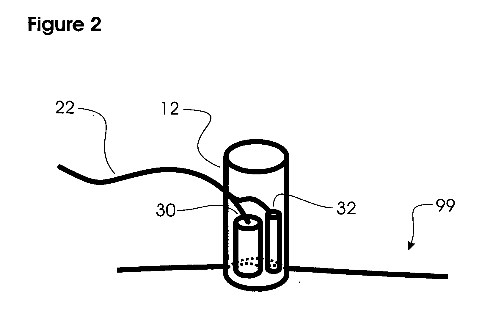
[0054] Preferred embodiment of this invention as an apparatus, as shown in FIG. 1, involves a moveable probe 12 and a set of sonic transducers 14. The probe 12 comprises a sonic sound transmitter 30 (as in FIG. 2), such as a piezoelectric crystal, which generates an intensity waveform of sound, such as an impulse or several cycles of high frequency sound, at regular intervals. In FIG. 1, the transmitted waveform follows direct paths 28 from the sound transmitter 30 to each of the sonic transducers 14. Each sonic transducer, functioning as a microphone, converts the received sonic waveform into an electrical waveform.

[0055] The sonic waveform transmitted by sonic transmitter 30 (shown in FIG. 2) is initiated by an electronic timing and control circuit 10, which concurrently resets one or more timers (such as a digital counter incrementing every microsecond or faster). The circuit 10 then registers the elapsed time when the sound waveform is received at each of the transducers 14 and...


PUM


Abstract

The method of this invention, and the apparatus which implements it, provides a way of sampling points on the surface of a portion of a rigid or semi-rigid object, which might be an anatomical body. Points are sampled by a moveable contact probe which emits a sonic waveform under the direction of a control unit. Multiple fixed sonic transducers in contact with the object at diverse locations detect the waveform, the arrival of which is timed for each transducer by the control unit. Given the speed of sound in the object and the coordinates of the transducers, a digital computer can compute the location of the probe. Two ways are presented to calibrate the locations of the transducers. Provision is made for mitigating possible distortion of soft object surfaces due to the contact force of the probe. During the sampling of probe contact locations, at least one physical or physiological attribute is also acquired. Sampling sufficient points allows 3-d geometric construction of a model of the portion, which includes both the surface shape geometry and the distribution of the values of the attribute thereon. Finally a view of the model may be rendered on a graphical display medium.

Description

CROSS-REFERENCE TO RELATED APPLICATIONS [0001] not applicable FIELD OF INVENTION [0002] This invention relates to an improvement for acquiring 3-dimensional geometrical and localized physical measurements from portions of a solid, rigid or semi-rigid object and for relating each physical datum to the geometrical location at which it was acquired. In particular, the solid object could be a portion of an anatomical body, such as a human limb for example. BACKGROUND [0003] Various systems, using various technologies, have been documented, developed, and patented for measuring the surface geometry of and spatial locations on physical objects, where the objects may be portions of animal or human anatomy. Such measurement systems also include those which yield full, 3-dimensional internal cross-sectional images, from which the surface shape information may be derived. [0004] Examples of the latter systems are CT (computed tomography imaging), MRI (magnetic resonance imaging), and diagnost...

Claims


Application Information

Patent Timeline
IPC IPC(8): A61B5/06A61B8/08G01B17/00
CPCA61B5/06A61B8/4472A61B8/0833A61B5/062A61B5/067
Inventor SCHULZ, WALDEAN
Owner CONCEPTUAL ASSETAB
Why Eureka
Try Eureka