
Weight detecting apparatus with vibrational sensors attached to both the free end and the fixed end of the load cell

a vibration sensor and weight detecting technology, applied in the field of weight detecting equipment, can solve the problems of device not having a component or structure, device not having a structure, etc., and achieve the effect of reducing detection precision, reducing detection precision, and eliminating influen

Inactive Publication Date: 2005-11-17
ISHIDA CO LTD
View PDF10 Cites 0 Cited by
  • Summary
  • Abstract
  • Description
  • Claims
  • Application Information

AI Technical Summary

Benefits of technology

[0008] In the weight detecting apparatus disclosed in the patent reference 1, if the object table C is formed of the transporting conveyor C1 as disclosed, e.g., in the patent reference 2, vibration components that originate from the transporting conveyor C1 are superimposed on the detection signal of the weight detecting load cell A1. However, the device does not have a component or structure for removing the vibration components occurring on the object placing side. This lowers the detection precision.
[0009] In the weight detecting apparatus disclosed in the patent reference 2, vibration components of the vibration of the fixed base B are superimposed on the detection signals of the weight and vibration detecting load cells A1 and A3. However, the device does not have a component or structure for removing the vibration components occurring on the device installation side. This likewise lowers the detection precision.
[0010] In view of the above, it is an object of the invention to provide a weight detecting apparatus, which can eliminate an influence due to vibration disturbance exerted from the device installation side and the object placing side, and thereby can improve the detection precision.
[0012] According to the first invention, the first and second vibration detecting means detect the vibration components on the fixed end side and the free end side of the weight detecting means, and the vibration components thus detected are removed from the detection signal of the weight detecting means so that only the signal matching with the weight of the object can be obtained, and the object weight can be detected with improved precision.

Problems solved by technology

However, the device does not have a component or structure for removing the vibration components occurring on the object placing side.
This lowers the detection precision.
However, the device does not have a component or structure for removing the vibration components occurring on the device installation side.
This likewise lowers the detection precision.

Method used


Image

  • Weight detecting apparatus with vibrational sensors attached to both the free end and the fixed end of the load cell
  • Weight detecting apparatus with vibrational sensors attached to both the free end and the fixed end of the load cell
  • Weight detecting apparatus with vibrational sensors attached to both the free end and the fixed end of the load cell

Examples


Embodiment Construction

[0028] A weight detecting apparatus according to an embodiment of the invention will now be described.

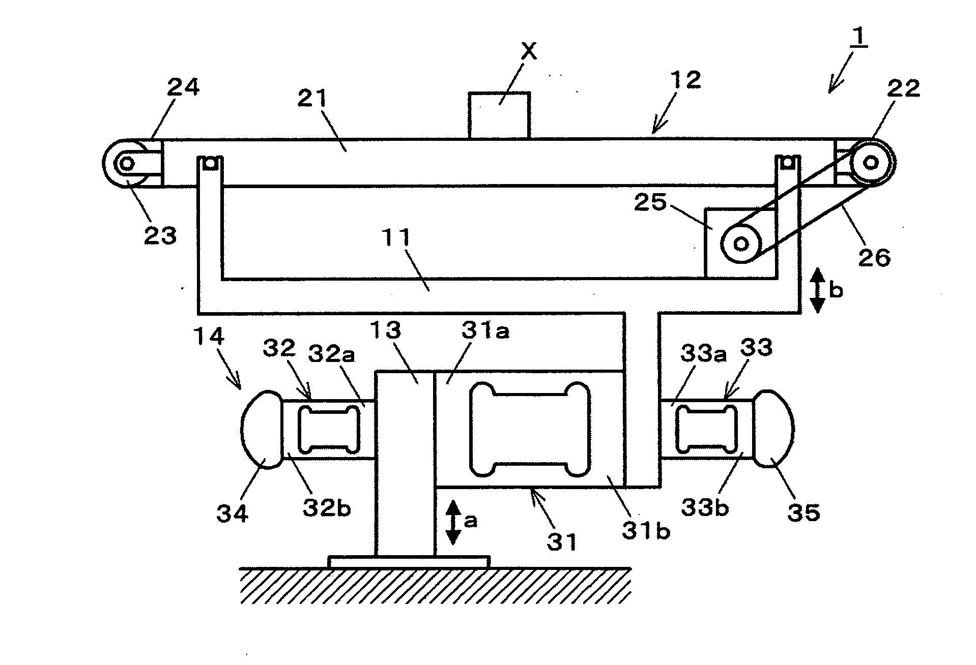
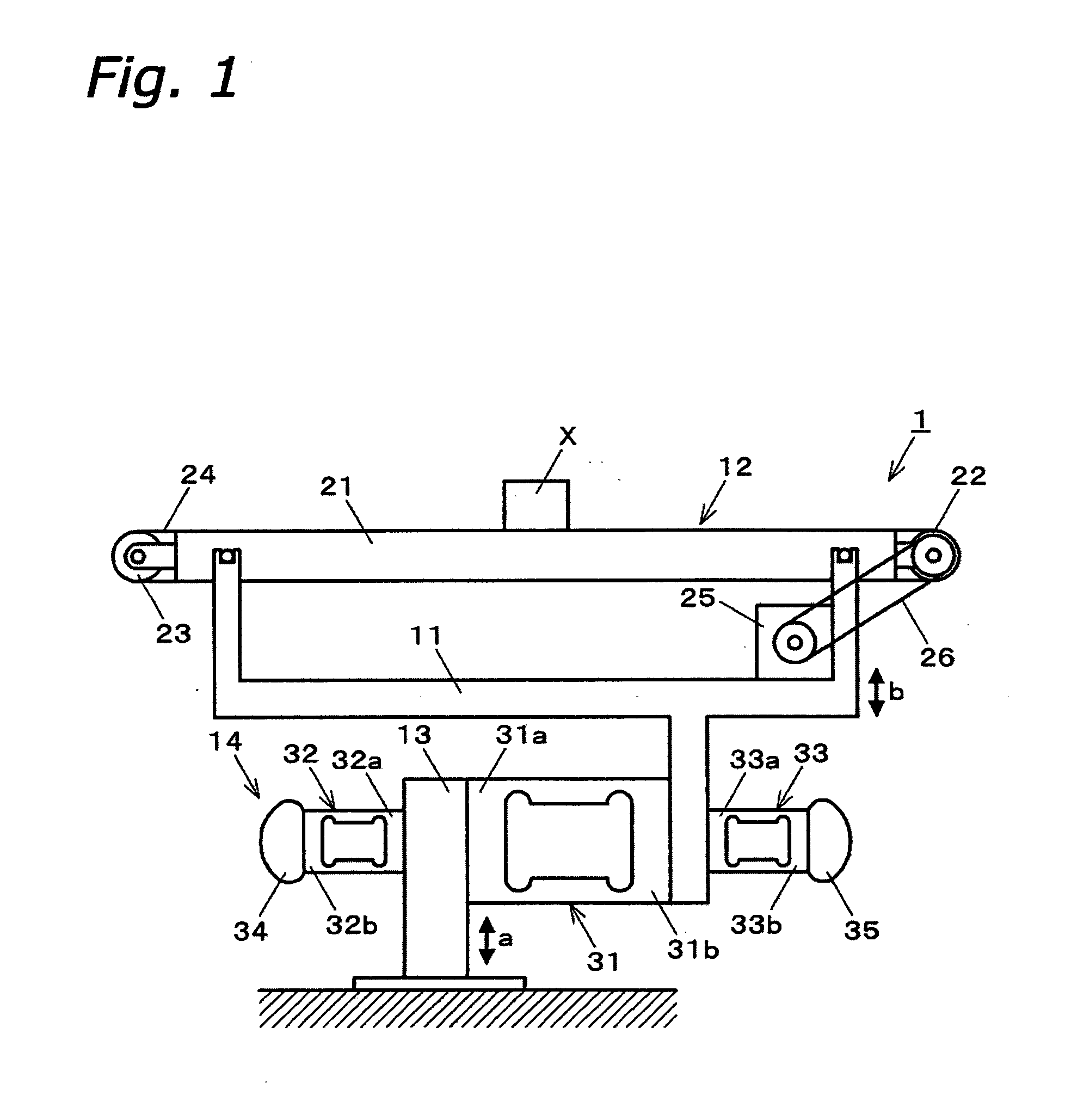
[0029] As shown in FIG. 1, a weight detecting apparatus 1 has a transporting conveyor 12 supported by upper portions of a support frame 11, and a weight detecting mechanism 14. The weight detecting mechanism 14 is coupled to the support frame 11, and is mounted on a fixed base 13 arranged on a floor. The weight detecting mechanism 14 detects a weight of an object X, which is transported on the transporting conveyor 12.

[0030] The transporting conveyor 12 has a pair of rollers 22 and 23, i.e., a front drive roller 22 and a rear driven roller 23, which are rotatably carried between a pair of side frames 21, only one of which is shown. The transporting conveyor 12 also has an endless belt 24 passing around the rollers 22 and 23. The support frame 11 supports a motor 25 serving as a transportation drive source. A timing belt 26 is arranged around an output pulley, which is fixed coaxia...


PUM


Abstract

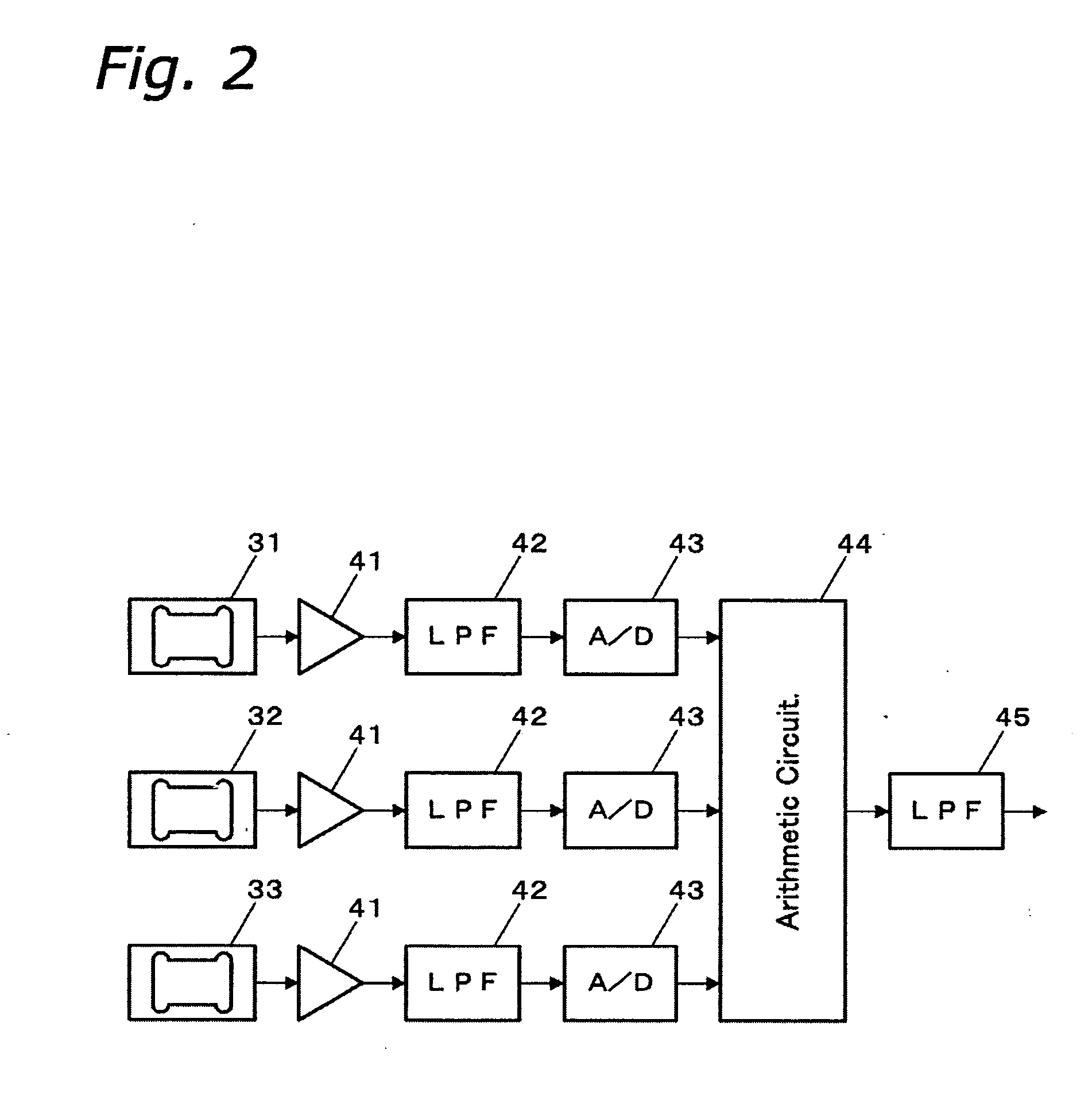
The invention provides a weight detecting apparatus, which can eliminate an influence by vibration disturbance exerted from a device installation side and an object placing side, and thereby can improve detection precision. The weight detecting apparatus includes a weight detecting load cell (31) having a fixed end (31a) fixed to a fixed base (13) arranged on a floor and a free end (31b) bearing a weight of an object (X), a first vibration detecting load cell (32) arranged on the fixed end (31a) side of the weight detecting load cell (31) for detecting a vibration component on the fixed end (31a) side, i.e., a floor vibration component, and a second vibration detecting load cell (33) arranged on the free end (31b) side of the weight detecting load cell (31) for detecting a motor vibration component on the free end (31b) side, i.e., the motor vibration component. The weight detecting apparatus precisely detects the weight of the object (X) by removing the vibration component from the detection signal of the weight detecting load cell (31) based on the detection signals of the respective load cells (31-33).

Description

FIELD OF THE INVENTION[0001] The present invention relates to a weight detecting apparatus, and particularly to a weight detecting apparatus for detecting a weight of an object placed thereon with high precision, and belongs to a field of weight detecting technology. DESCRIPTION OF THE BACKGROUND ART [0002] Weight detecting apparatuses, which detect weights of objects by weight detectors such load cells, have been widely used in various fields. Patent reference 1 (Japanese Laid-Open Patent Publication No. H8-110261) and patent reference 2 (Japanese Laid-Open Patent Publication No. H8-136330) have disclosed examples of weight detecting apparatuses, which are configured to eliminate disturbance due to vibrations for further improving detection precision. [0003] Referring to FIG. 5, the weight detecting apparatus disclosed in the patent reference 1 includes a weight detecting load cell (load cell for measurement) A1 and a vibration detecting load cell (load cell for dummy) A2, which ar...

Claims


Application Information

Patent Timeline
Patent Type & Authority Applications(United States)
IPC IPC(8): G01G11/00G01G23/10G01G23/01
CPCG01G23/10
Inventor WAKASA, YUKIO
Owner ISHIDA CO LTD
Learn More