
Technique for enhancing effectiveness of cache server

a cache server and efficiency technology, applied in the field of network system and cache server, can solve the problems of ineffective operations, waste of network resources, and inability to carry out operations (1), (2) and (3), and achieve the effect of increasing the efficiency of the cache server, shortening the time taken for obtaining data, and increasing probabilities

Inactive Publication Date: 2005-11-03
NEC CORP
View PDF9 Cites 70 Cited by
  • Summary
  • Abstract
  • Description
  • Claims
  • Application Information

AI Technical Summary

Benefits of technology

[0032] It is, therefore, an object of the present invention to provide techniques for increasing the efficiency of a cache server by performing a link prefetching operation, an automatic cache updating operation, and a cache server cooperating operation in higher probabilities than those of the prior art, without deteriorating a congestion status of the network.
[0033] The object of the present invention can be achieved by making the cache server know the network topology of routers and links within a network and the load status of each link and thereby to take a path by bypassing high-load links, lowering the traffic priority of the high-load link, or relaying data using low-load links.

Problems solved by technology

When the predicted content are not actually required, or when the content is updated more frequently at the Web server than the automatic cache updating operation, these operations are not effective.
Only the resources of the network are wasted.
Consequently, there has been a problem that the operations of (1), (2) and (3) are not carried out.
As a result, the prefetching of the content may further deteriorate the congestion status of the network.

Method used


Image

  • Technique for enhancing effectiveness of cache server
  • Technique for enhancing effectiveness of cache server
  • Technique for enhancing effectiveness of cache server

Examples


first embodiment

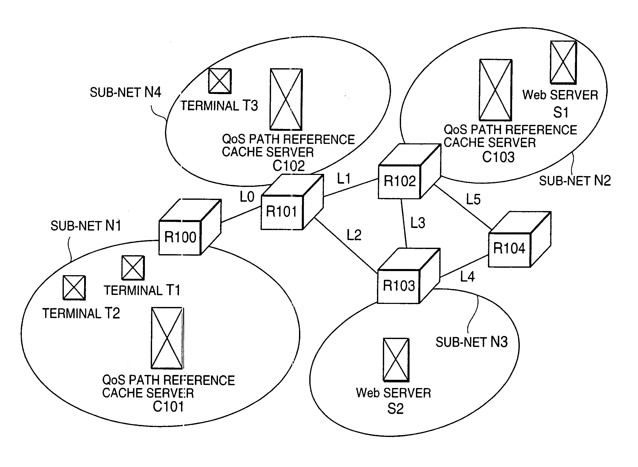
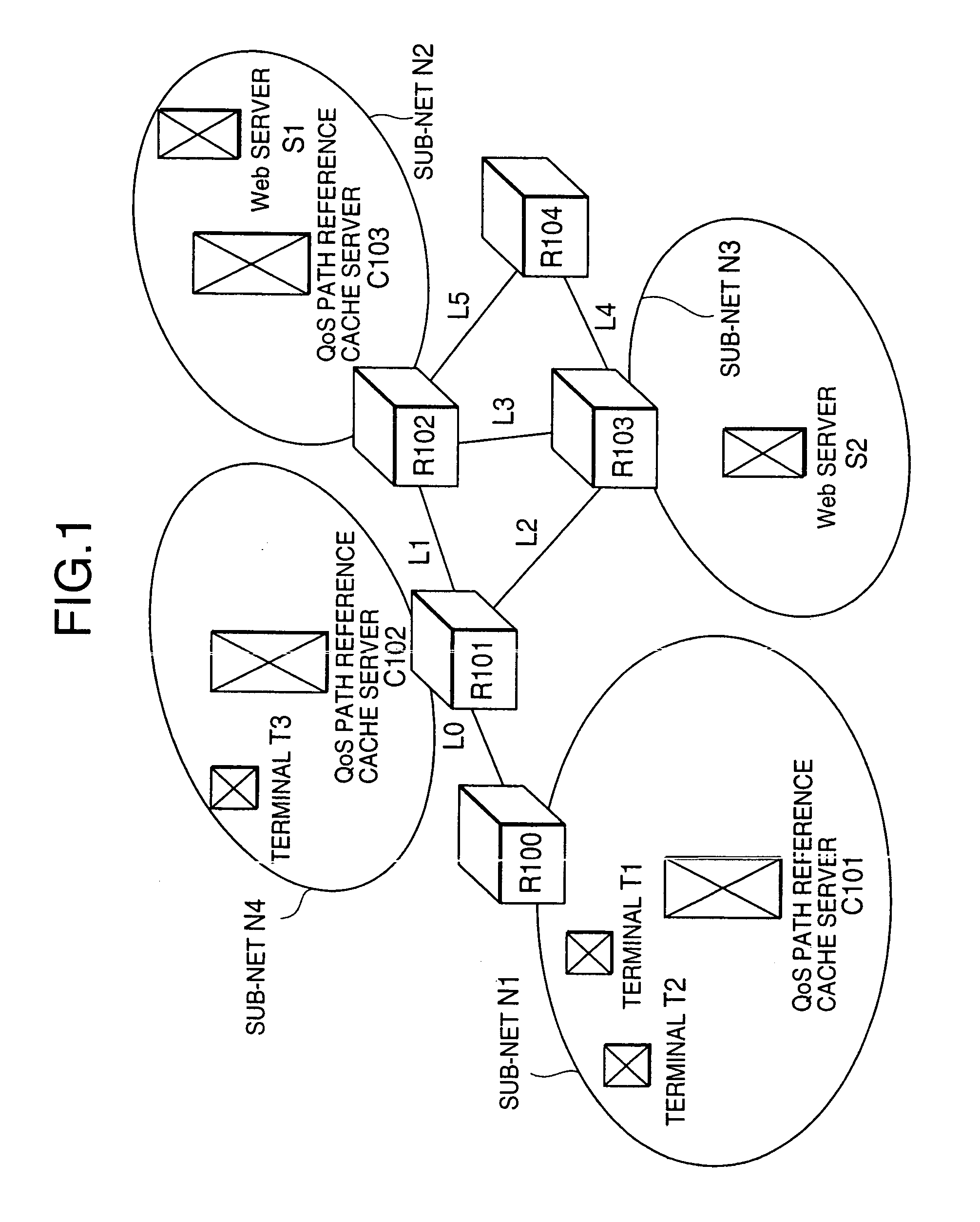
[0079]FIG. 1 shows the configuration of a network system according to a first embodiment of the present invention. Web servers S1 and S2 exist within sub-nets N2 and N3 respectively, and hold various Web content information. Terminals T1, T2 and T3 for accessing the Web servers S1 and S2 exist within sub-nets N1 and N4. QoS (Quality of Service) path reference cache servers C101 to C103 are also disposed on the network. The QoS path reference cache servers C101 to C103 hold copies of various content on the Web servers S1 and S2 that have been accessed from the terminals T1 to T3 and other cache servers (QoS path cache servers or conventional cache servers are not shown). In addition, the QoS path reference cache servers C101 to C103 are designed to obtain QoS path information that includes pairs of names of links and routers that are connected with each other, bandwidth of each link, and remaining bandwidth of each link.

[0080] The QoS path information maybe obtained by communicating...

second embodiment

[0107]FIG. 6 is a block diagram showing an example of a network system according to a second embodiment of the present invention. The second embodiment shown in FIG. 6 is different from the first embodiment shown in FIG. 1 in that the routers R100 to R104 are replaced with path-settable routers R200 to R204, and that the QoS path reference cache servers C101 to C103 are replaced with QoS path reference cache servers C201 to C203.

[0108] The path-settable routers R200 to R204 have functions that are achieved by operating an MPLS protocol in addition to the functions of the routers R100 to R104. The path-settable routers R200 to R204 have functions for setting a path specified by the path information on the network, according to the path information received from the QoS path reference cache servers C201 to C203. The path information is composed of network addresses of two servers that communicate with each other, identifiers (port numbers and the like in a TCP / IP network) for identif...

third embodiment

[0117]FIG. 9 is a block diagram showing an example of a network system according to a third embodiment of the present invention. The network system of the third embodiment shown in FIG. 9 is the same as the conventional network system (see FIG. 36) except the followings. Namely, the cache servers C1 to C3 are replaced with QoS path reference relay control cache servers C301 to C303. Relay servers M301 and M302 are provided in the third embodiment. Further, the routers R0 to R4 are replaced with routers R100 to R104, which have the same functions as those of the routers R0 to R4. It may be so structured that the QoS path reference relay control cache servers take the role of the relay servers at the same time. In other words, it may be so designed that the functions of QoS path reference relay control cache server and relay server are built into one casing. Further, it may also be so designed that the functions of router, QoS path reference relay control cache server, and relay serve...


PUM


Abstract

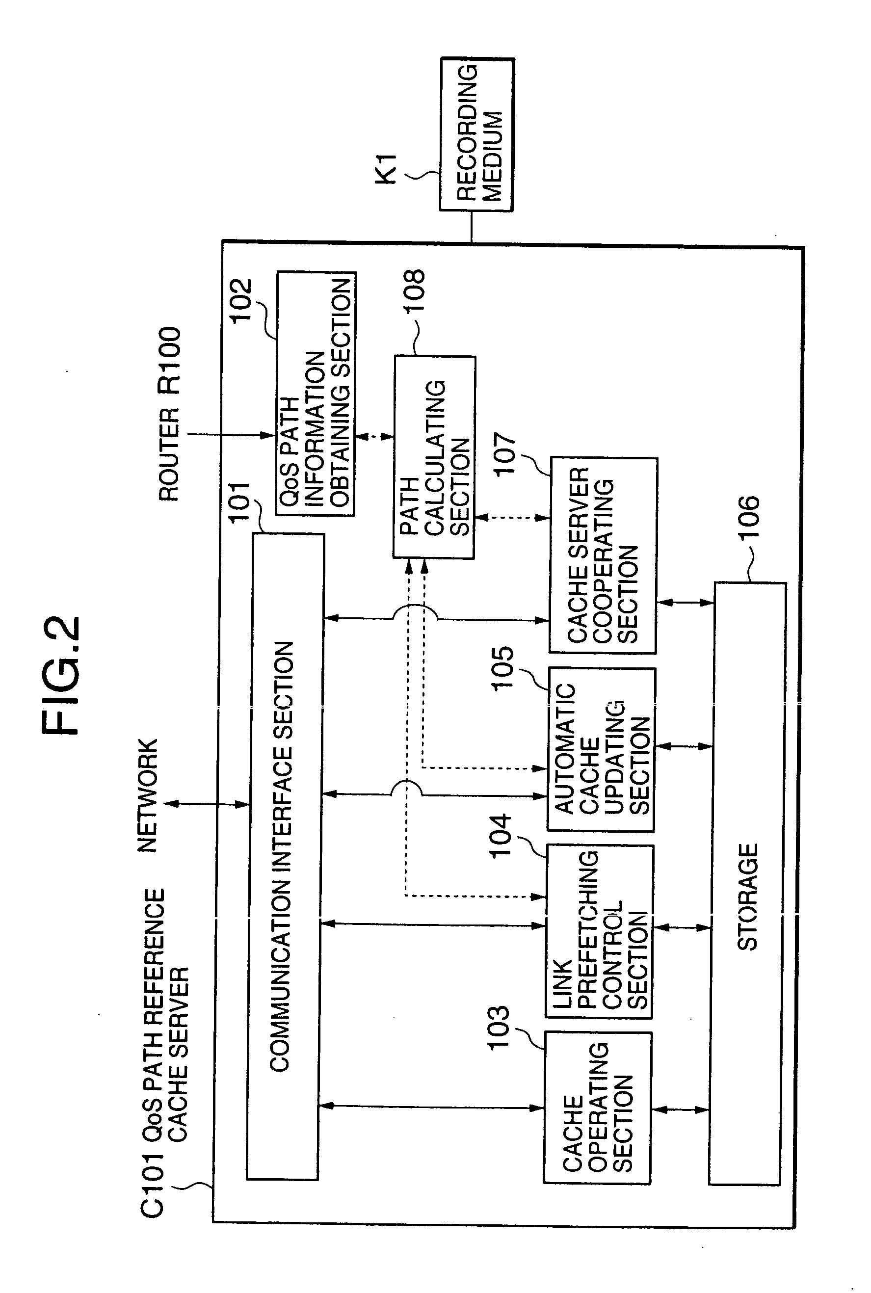
A path calculating section obtains a path suitable for carrying out an automatic cache updating operation, a link prefetching operation, and a cache server cooperating operation, based on QoS path information that includes network path information and path load information obtained by a QoS path information obtaining section. An automatic cache updating section, a link prefetching control section, and a cache server cooperating section carry out respective ones of the automatic cache updating operation, the link prefetching operation, and the cache server cooperating operation, by utilizing the path obtained. For example, the path calculating section obtains a maximum remaining bandwidth path as the path.

Description

CROSS-REFERENCE TO RELATED APPLICATIONS [0001] This is a continuation of U.S. patent application Ser. No. 09 / 915,056, filed Jul. 25, 2001, in the name of Masayoshi Kobayashi, and entitled TECHNIQUE FOR ENHANCING EFFECTIVENESS OF CACHE SERVER.BACKGROUND OF THE INVENTION [0002] 1. Field of the Invention [0003] The present invention relates to a cache server and a network system having cache servers. The invention particularly relates to a technique of performing prefetching of linked information (link prefetching) and the like with enhanced effectiveness of a cache server in high probabilities without deteriorating a congestion status of the network. [0004] 2. Description of the Related Art [0005] A conventional network system having cache servers will be described with reference to FIG. 36 and FIG. 37. [0006]FIG. 36 is a block diagram showing an example of the configuration of a conventional network system having cache servers. Web servers S1 and S2 are the servers that exist within ...

Claims


Application Information

Patent Timeline
Patent Type & Authority Applications(United States)
IPC IPC(8): G06F13/00G06F12/00G06F17/30H04L29/08
CPCG06F17/30902H04L67/2804H04L67/2852H04L67/322H04L67/2847G06F16/9574H04L67/561H04L67/5681H04L67/5682H04L67/61
Inventor KOBAYASHI, MASAYOSHI
Owner NEC CORP
Learn More