
Multicarrier modulation systems

a multi-carrier, modulation system technology, applied in modulated-carrier systems, transmission, complex mathematical operations, etc., can solve the problems of limited dynamic range of fixed-point systems, limitation of the practical implementation of multi-carrier modulation systems, and account for limitations due to arithmetic processing, etc., to achieve the effect of minimizing degradation

Active Publication Date: 2005-11-03
ANALOG DEVICES INT UNLTD
View PDF12 Cites 95 Cited by
  • Summary
  • Abstract
  • Description
  • Claims
  • Application Information

AI Technical Summary

Benefits of technology

[0021] A method of transmitting and receiving data in a multicarrier modulation system having a transmitter and a receiver each with an input, a calculation block and an output; the calculation block of at least one of the transmitter or receiver having a a plurality of interconnected calculation stages for undertaking numerical calculation on a signal received at the input and at least one scaling portion for maintaining numerical calculation substantially within an active window, and providing output derived from signal received at the input according to said numerical calculation; the method including allowing a predetermined low probability of saturation of signals beyond the active window by the scaling within the calculation block of any or both of the transmitter and receiver structures. Saturation can be allowed in a predetermined plurality of calculation stages of the calculation block.
[0031] The invention also provides a method of transmitting and receiving data in a multicarrier modulation system having a transmitter and a receiver for respectively transmitting and receiving signals, the transmitter and receiver having a plurality of inputs each for receiving an input number comprising a real or imaginary number related to a portion of a signal, a calculation block for undertaking a numerical transform of the plurality of received input numbers, and a plurality of outputs each for providing an output number comprising a real or imaginary number derived from the input numbers according to the numerical transform; the calculation block undertaking the numerical transform and comprising a plurality of interrelated calculation stages for undertaking numerical operations on numbers derived from the input numbers related to a portion of the signal, and the calculation block further comprising at least one scaling portion for undertaking scaling of one or more numbers within the calculation block to maintain the numbers substantially within the predetermined range of the active window throughout the numerical transform; the method including the scaling by the at least one scaling portion allowing a predetermined low probability of saturation of numbers within the calculation block beyond the range of the active window and clipping said saturated numbers to the extent of the active window.
[0032] The invention provides a new approach which is better suited to FFT design as applied to multicarrier modulation systems such as OFDM. The signals are scaled so that overflow, rather than being completely avoided, occurs with low probability throughout the IFFT and FFT structures. The size of the error that results from an overflow depends on how overflow is handled in the DSP. To minimize the degradation, overflow should result in saturation of the value at the maximum positive or negative value option. This is equivalent to clipping the signal. Using the new technique, signals within the FFT structure are scaled to balance the effect of clipping and round-off. Clipping may result in comparatively large errors in a few signal values but because of the spreading effect of the FFT and because OFDM systems typically include error coding / correction, system performance depends on the total error or, in other words the total noise power, across all of the FFT outputs rather than on any individual value.
[0036] The invention allows the minimum error rate to be achieved for a given arithmetic processing , or the arithmetic processing to be minimized for a given maximum error rate. By reducing the number of bits necessary it also allows novel structures such as where two eight bit numbers are represented within a 16 bit word length, thus reducing the number of operations required to implement the FFT / IFFT.
[0037] The invention can also be used within the extra FFT / IFFT operations used within peak to average power reduction techniques and impulse mitigation techniques which can be used in OFDM. The invention can also include use of oversized transforms to make filtering easier. It can also include the use of transforms with some inputs and or outputs zero such as in OFDMA (orthogonal frequency division multiple access) or use in OFDM systems using multiple antennas including multiple input multiple output systems

Problems solved by technology

There are various design issues which limit the practical implementation of multicarrier modulation systems.
A design issue is to account for limitations due to arithmetic processing.
However, fixed-point systems have limited dynamic range, causing the related problems of round-off noise and arithmetic overflow.
However the requirements in OFDM are significantly different from those in most FFT applications.
This contributes a small error at each butterfly.
Thus there is a conflict between minimizing the probability of saturation and minimizing the error due to truncation such as rounding.
The design problem is then to design the scaling so that there is the optimum trade-off between clipping and truncation such as rounding errors, given the statistical distribution of signals.
For OFDM systems using larger FFTs and fixed-point implementation, a large word length is required if rounding errors are not going to significantly degrade system performance.
Scaling is usually distributed throughout the FFT structure as this reduces the overall effect of rounding errors.
However a single large signal sample can result in scaling which causes large round off errors in all of the other signal values.

Method used


Image

  • Multicarrier modulation systems
  • Multicarrier modulation systems
  • Multicarrier modulation systems

Examples


Embodiment Construction

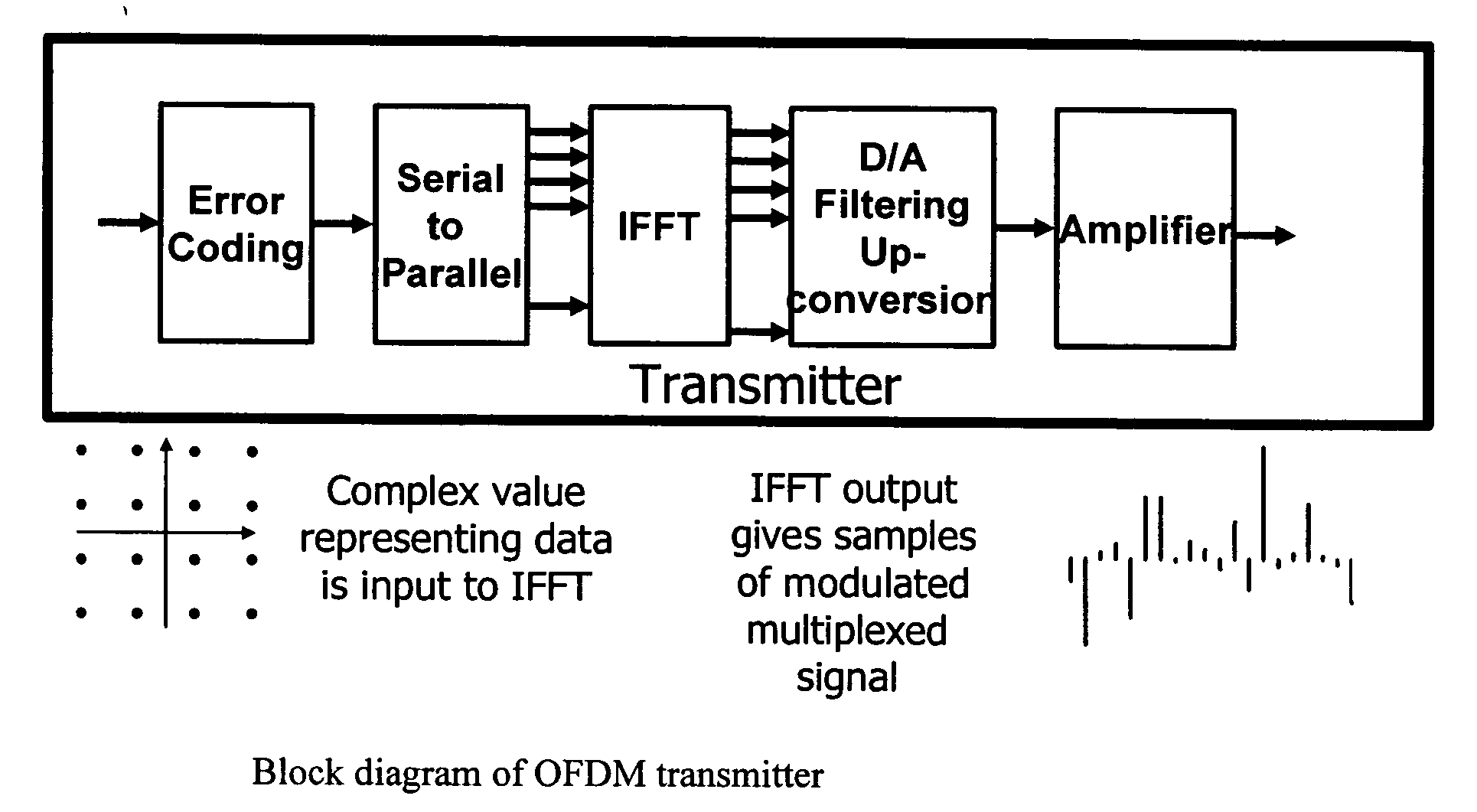
[0073] Embodiments of the invention are described in relation to orthogonal frequency division multiplexing (OFDM) systems, which are a particularly popular type of multicarrier system in which discrete Fourier transforms are used to perform modulation and demodulation.

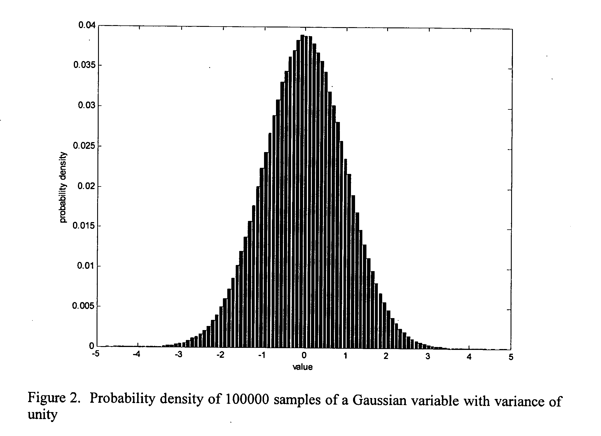
[0074] In order to understand and analyze the new technique, background information is required on a number of different topics. These are: [0075] i. Signal characteristics [0076] ii. OFDM, and in particular the effects of noise in OFDM; [0077] iii. FFT structures and fixed-point implementation and the effect of limited arithmetic precision; [0078] iv. the statistics of signals within the IFFT / FFT in OFDM; [0079] v. and the quantization of Gaussian signals.

[0080] This background is given in the following description and simulation results are presented for the new technique and compared with the results for conventional techniques. The practical implementation of the new technique on a fixed-point DSP is also presen...


PUM


Abstract

The invention provides a new approach which is better suited to FFT design as applied to multicarrier modulation systems such as OFDM. The signals are scaled so that overflow, rather than being completely avoided, occurs with low probability throughout the IFFT and FFT structures. The size of the error that results from an overflow depends on how overflow is handled in the DSP. To minimize the degradation, overflow should result in saturation of the value at the maximum positive or negative value option. This is equivalent to clipping the signal. Using the new technique, signals within the FFT structure are scaled to balance the effect of clipping and round-off. Clipping may result in comparatively large errors in a few signal values but because of the spreading effect of the FFT and because OFDM systems typically include error coding / correction, system performance depends on the total error or, in other words the total noise power, across all of the FFT outputs rather than on any individual value.

Description

CROSS REFERENCE TO RELATED APPLICATIONS [0001] The present application is related to and claims priority from U.S. Provisional Application No. 60 / 575,166, filed May 28, 2004, entitled “Improvements in Multicarrier Modulation Systems,” which is hereby incorporated by reference in its entirety. The present application is also related to and claims priority from Australian Provisional Application No. 2004902303, filed Apr. 30, 2004, entitled “Data Transmission and Reception in Multicarrier Modulation Systems,” which is hereby incorporated by reference in its entirety. The present application is further related to and claims priority from Australian Provisional Application No. 2004902888, filed May 31, 2004, entitled “Improvements in Multicarrier Modulation Systems,” which is hereby incorporated by reference in its entirety. The present application is still further related to and claims priority from Australian Provisional Application No. 2004904173, filed Jul. 26, 2004, entitled “Effec...

Claims


Application Information

Patent Timeline
IPC IPC(8): G06F17/14H04J11/00H04L27/00H04L27/26
CPCG06F17/142H04L27/263H04L27/265H04L27/2624H04L27/2651
Inventor ARMSTRONG, JEANBREWER, SIMON W.
Owner ANALOG DEVICES INT UNLTD
Learn More