Voltage-controlled oscillator with four terminal varactors

a voltage-controlled oscillator and varactor technology, applied in the direction of oscillator generators, angle modulation by variable impedence, electrical apparatus, etc., can solve the problems of poor linearity of frequency relative to control voltage, limited capacitor tuning, small tuning range, etc., and achieve the effect of increasing the frequency tuning range of the vco circui

Inactive Publication Date: 2005-11-03
LOTFI YOUNES
View PDF6 Cites 7 Cited by
  • Summary
  • Abstract
  • Description
  • Claims
  • Application Information

AI Technical Summary

Benefits of technology

[0005] The present invention provides a VCO capable of controlling VCO gain magnitude and gain linearity, which in turn allows the loop bandwidth of the PLL to be controlled electrically with the VCO circuit and increases the frequency tuning range for the VCO circuit.

Problems solved by technology

In these types of varactors, however, the capacitance tuning is limited due to fixed capacitance such as side-wall capacitance and parasitic PN junction capacitance.
Limited capacitance tuning results in a smaller tuning range and poor linearity of frequency relative to the control voltage.

Method used


Image

  • Voltage-controlled oscillator with four terminal varactors
  • Voltage-controlled oscillator with four terminal varactors
  • Voltage-controlled oscillator with four terminal varactors

Examples


Embodiment Construction

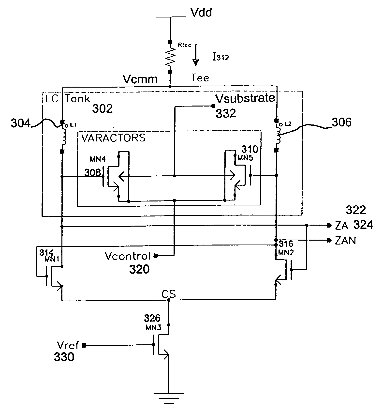
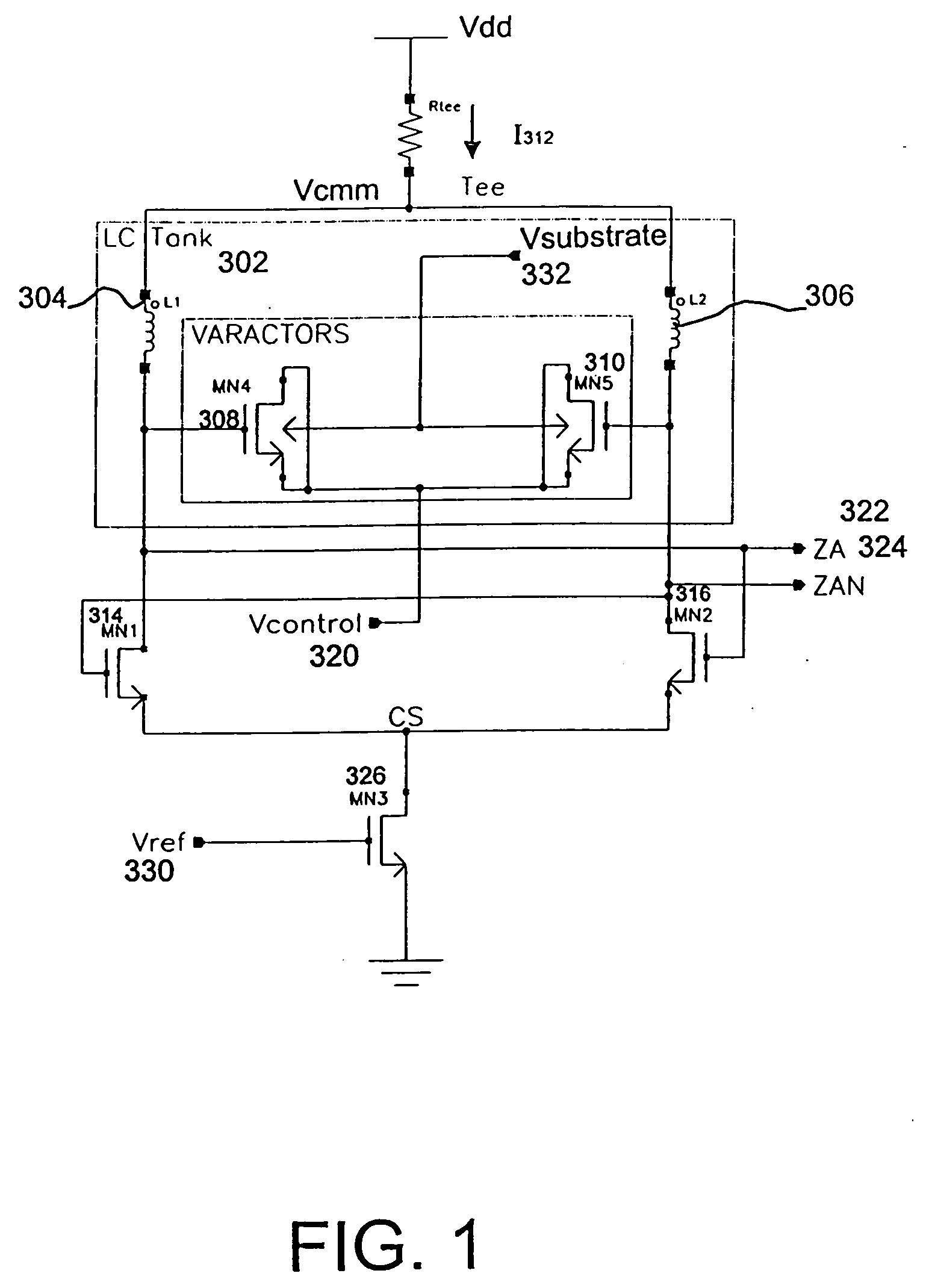
[0022]FIG. 1 illustrates an electrical schematic of an embodiment of an LC tank-based VCO having four terminal varactors in accordance with aspects of the invention. In one embodiment, a VCO includes an LC tank 302 having inductors L1304 and L2306 and varactors MN4308 and MN5310. The varactors provide variable capacitance. Input end of the inductors L1304 and L2306 are coupled to a resistor, Rtee, and a voltage source, Vdd.

[0023] In the embodiment of FIG. 1, the varactors are four terminal N-channel MOSFET devices, MN4308 and MN5310, each having a gate terminal, a drain terminal, a source terminal and a substrate (also referred to as bulk) terminal. With respect to MN4308, the gate terminal is coupled to the output end of the inductor L1304. The gate terminal is also coupled to an output node ZA 322 and the drain terminal of an N-channel MOSFET device MN1314. The drain and the source terminals of MN4308 are coupled to a first control voltage Vcontrol 320. In some embodiments, Vcont...


PUM


Abstract

A voltage-controlled oscillator (VCO) capable of controlling VCO gain magnitude, VCO frequency tuning range and gain linearity, which in turn allows the loop bandwidth of a phase-locked loop to be controlled electrically with the VCO circuit and increases the frequency tuning range for the VCO circuit. An embodiment includes a voltage-controlled oscillator comprising an LC tank having a plurality of varactors, each of the plurality of varactors having four terminals. At least one of the terminals is coupled to a first control signal and one of the terminals is a substrate terminal coupled to a second control signal.

Description

BACKGROUND OF THE INVENTION [0001] The present invention relates generally to voltage-controlled oscillators, and more particularly to LC tank voltage-controlled oscillators. [0002] A phase-locked loop (PLL) is a component widely used in wireless communication systems. A PLL generates a clock signal using a received data stream. The clock signal has the same phase and frequency (or multiple of the frequency) as the received data stream. For example, in a receiving unit of a digital data communication system, to recover transmitted data, a PLL in the receiving unit synchronizes an internal clock of the receiving unit to the frequency and phase of the received data. Clock multiplication units, frequency synthesizers and clock recovery circuits are common applications of a PLL. [0003] An oscillator, such as a voltage-controlled oscillator (VCO) is generally used in PLL's to generate a controllable clock signal. A VCO has an oscillation frequency controllable by the application of a con...

Claims


Application Information

Patent Timeline
Patent Type & Authority Applications(United States)
IPC IPC(8): H03B5/00H03B5/12
CPCH03B5/1228H03B5/1293H03B5/1253H03B5/1215
Inventor LOTFI, YOUNES
Owner LOTFI YOUNES
Why Eureka
Try Eureka