Load Cell Insensitive to Angular Misalignments and Shock Loads

Inactive Publication Date: 2005-11-03
METTLER TOLEDO INC
View PDF1 Cites 2 Cited by
  • Summary
  • Abstract
  • Description
  • Claims
  • Application Information

AI Technical Summary

Benefits of technology

[0016] An object of the present invention is to incorporate a spring into a load cell, reducing its stiffness such that mounting misalignments, shock loads and overload stop setting are less of a problem than in current designs.
[0017] The inventor of the present invention has come up with a new load cell design that is less sensitive to misalignments of the members applying the load. The new design is much less likely to be damaged by shock loads as it is inherently more compliant than commercial designs. Overload stop setting is much easier on this cell, as the deflection of this cell, compared to commercial cells, is large between the point of rated capacity and failure. The incorporated spring adds very little to the size of the load cell and is much smaller than an assembly in which a spring could be added to a commercially-available load cell.

Problems solved by technology

One frequent complaint about S-cells is that they produce an output in response to moments applied at their ends.
This output is undesired as we would prefer to have an output due only to the compression or tension in a two force member.
However, the cell is rarely a real two force member in that moments are usually applied, either intentionally or unintentionally.
Therefore, the cells usually produce an output proportional to both the load and the moment and it is impossible to know how much of the output comes from the load and how much comes from the moment.
In tension, various approaches are used to reduce the applied moment and hence, the error caused by it.
All these approaches add cost and require more space for mounting.
In compression, the problem of eliminating moments is more difficult.
If the object applying the compressive load is not constrained properly, using spherical bearings or long rods / cables is impossible, as moments must be applied to the cell to prevent it from rotating.
Most S-cells will fail if they encounter axial loads 300% higher than their rated capacity.
In many cases, insufficient room exists for long rods and discrete springs are used, but these too require more space and mounting complexity.
This means that in some assemblies, the cell deflection would encounter an overload stop before reaching its rated capacity, giving the cell user an artificially low reading.

Method used


Image

  • Load Cell Insensitive to Angular Misalignments and Shock Loads
  • Load Cell Insensitive to Angular Misalignments and Shock Loads
  • Load Cell Insensitive to Angular Misalignments and Shock Loads

Examples


Embodiment Construction

[0021] The following description is demonstrative in nature and is not intended to limit the scope of the invention or its application of uses.

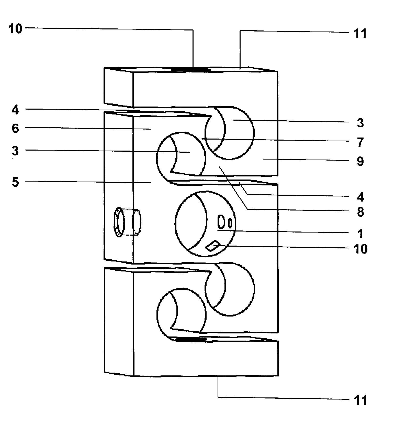
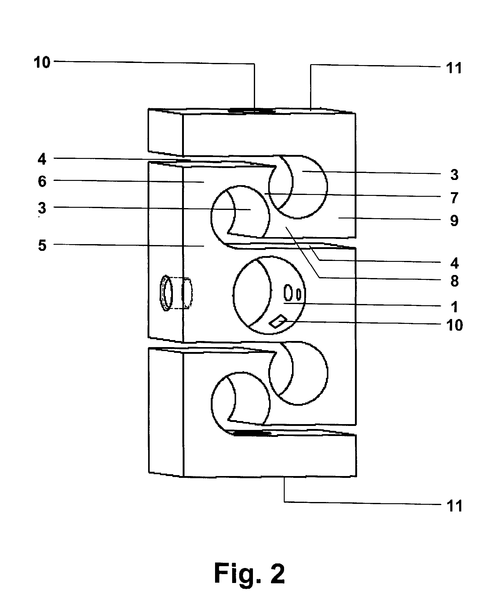
[0022] There are a number of significant design features and improvements incorporated within the invention. The current invention is a new load cell design incorporates an integral spring into the body of the load cell. Compared to a standard S-cell, this spring does not reduce the load carrying capacity of the cell. The spring increases the deflection of the cell, yielding less sensitivity to angular misalignments, shock loads and overload stop setting errors.

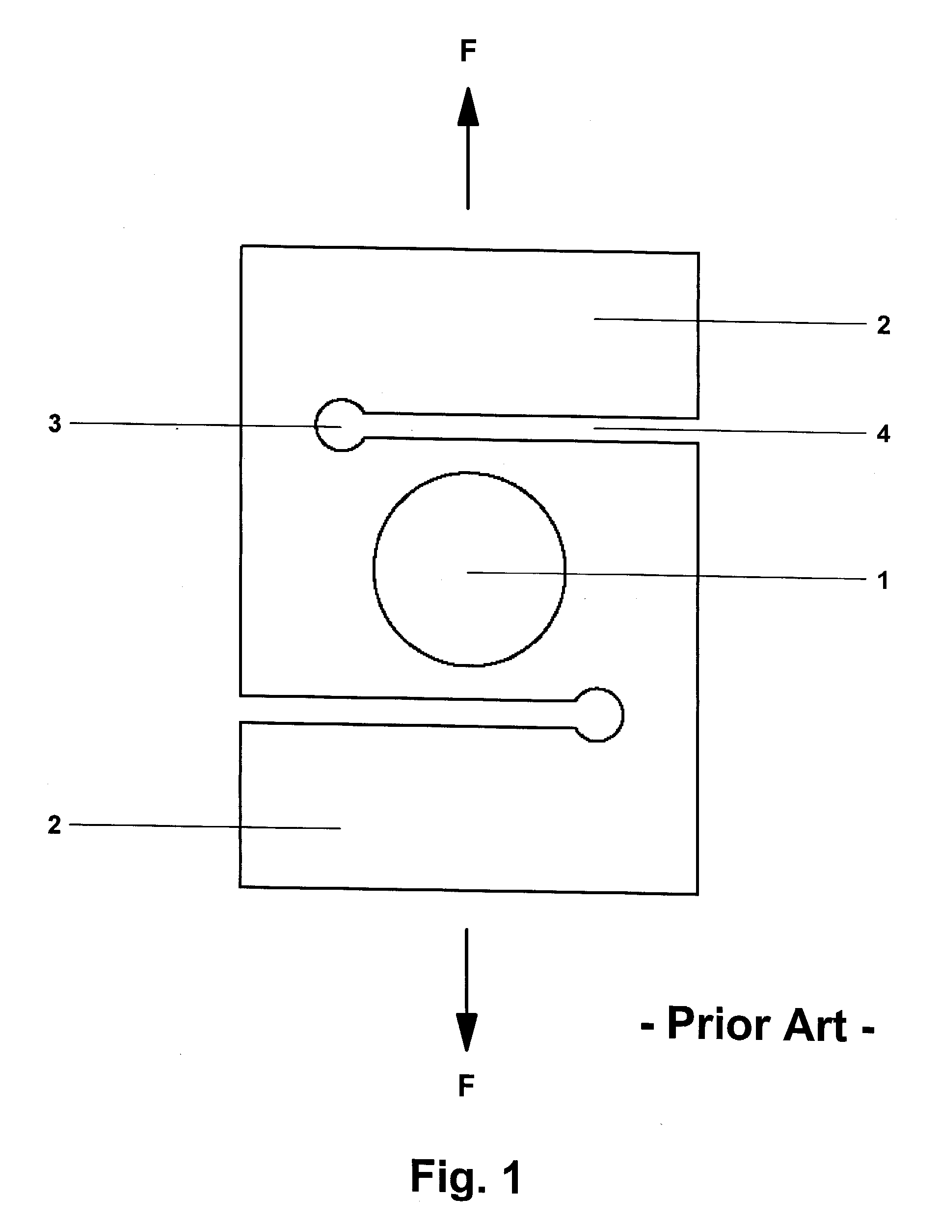
[0023] Referring initially to FIG. 1, there is shown an elevational side view of a prior art S-cell type load cell. The load is measured in the shear-measurement section 1. The arms 2 fold back over the shear measurement section such that the load F applied at the top is co-linear with the load F applied at the bottom arm. One hole 3 is drilled on each end of the cell at the end of t...


PUM


Abstract

A new load cell design incorporates an integral spring into the body of the load cell. Compared to a standard S-cell, this spring does not reduce the load carrying capacity of the cell. The spring increases the deflection of the cell, yielding less sensitivity to angular misalignments, shock loads and overload stop setting errors.

Description

BACKGROUND OF INVENTION [0001] 1. Field of the Invention [0002] This invention relates to load cells and more particularly to a load cell that provides a large deflection, rendering it insensitive to angular misalignments and shock loads. [0003] 2. Description of Prior Art [0004] There is a long history of load cells designed to measure shear. The first shear-type load cells were in the form of a beam with a section usually in the middle designed to measure the shear force in the beam. The shear measuring section often uses wire or foil type strain gages and a variety of shear measuring strategies have been devised. Currently there are 3 common types. These are: [0005] 1. Strain gages that are placed on or near the neutral axis of the beam and oriented in the principal direction, usually at 45°. [0006] 2. Strain gages are placed inside a either round or rectangular hole that measures the deformation of the hole under shear loading. Although the beam is in bending and shear, the chan...

Claims


Application Information

Patent Timeline
IPC IPC(8): G01N3/06G01N3/24
CPCG01N3/066
Inventor SCOOT, JON ZAN
Owner METTLER TOLEDO INC
Why Eureka
Try Eureka