
Wireless communication network and flow control method

Inactive Publication Date: 2005-10-27
FUJITSU LTD
View PDF24 Cites 46 Cited by
  • Summary
  • Abstract
  • Description
  • Claims
  • Application Information

AI Technical Summary

Benefits of technology

[0048] Accordingly, an object of the present invention is to so arrange it that efficient flow control (capacity-request start-up control) that is aware of the HS-PDSCH minimum receive interval can be implemented.
[0049] Another object of the present invention is to so arrange it that high-quality communication can be implemented by varying the HS-PDSCH minimum receive interval dynamically depending upon a difference in various operating conditions and causing the flow-control start-up period to fall in line with the minimum receive interval.
[0053] In accordance with the present invention, data flow control between a base station controller and a base station and sending / receiving of data between a base station and a mobile station can be carried out at the same time. As a result, transmission band and computation resources are no longer wasted.
[0054] In accordance with the present invention, it is so arranged that if the amount of mobile-station-directed data that has accumulated in a buffer increases, a base station controller performs flow control between itself and a base station and transmits data to the base station. This is advantageous in terms of apparatus size and cost because it is no longer necessary to install a large buffer.
[0055] In accordance with the present invention, the data receive interval of the mobile station is changed dynamically on a per-mobile-station basis in accordance with a change in communication conditions, e.g., number of times the mobile station has moved from one cell to another, communication quality, etc. As a result, optimum data flow control can be carried out for every mobile station.

Problems solved by technology

In this case, the transmission request is issued often and efficiency is poor in terms of the transmission band and computation processing resources.
Such flow control, however, has the problems set forth below.
This not only wastes the transmission band between the RNC and Node B but also leads to waste of computation resources expended in capacity-request processing within the RNC.
Furthermore, if data occupies the buffer in node B for a long period of time, a problem which arises is that the buffer will no longer be allocated to a data-transfer request (capacity request) issued subsequently by the RNC.
Installing a large buffer in order to solve this problem is disadvantageous in terms of the size and cost of the apparatus.
Furthermore, if data occupies the buffer in RNC 1 for a long period of time, there is a possibility that the buffer will be inadequate.
Installing a large buffer in order to solve this problem is disadvantageous in terms of the size and cost of the apparatus.
With a “fixed-period capacity-request processing start-up method” of the kind normally carried out, therefore, it is difficult to apply a capacity-request processing start-up period that is optimum for all UEs.
Although this prior art implements flow control of packets, it does not relate to flow control between a base station controller and a base station in a wireless communication network that includes a base station controller, base stations and mobile stations, and it does not exercise flow control based upon the data receive interval of a mobile station.

Method used


Image

  • Wireless communication network and flow control method
  • Wireless communication network and flow control method
  • Wireless communication network and flow control method

Examples


Embodiment Construction

[0072] (A) Overall Communication System

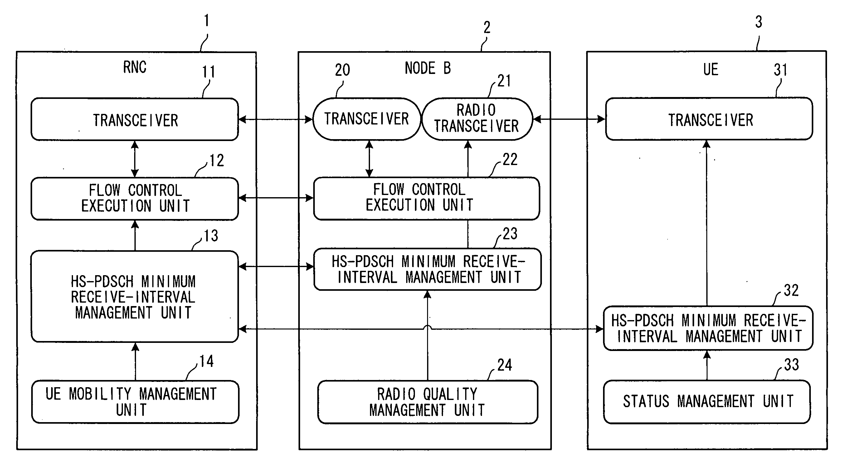
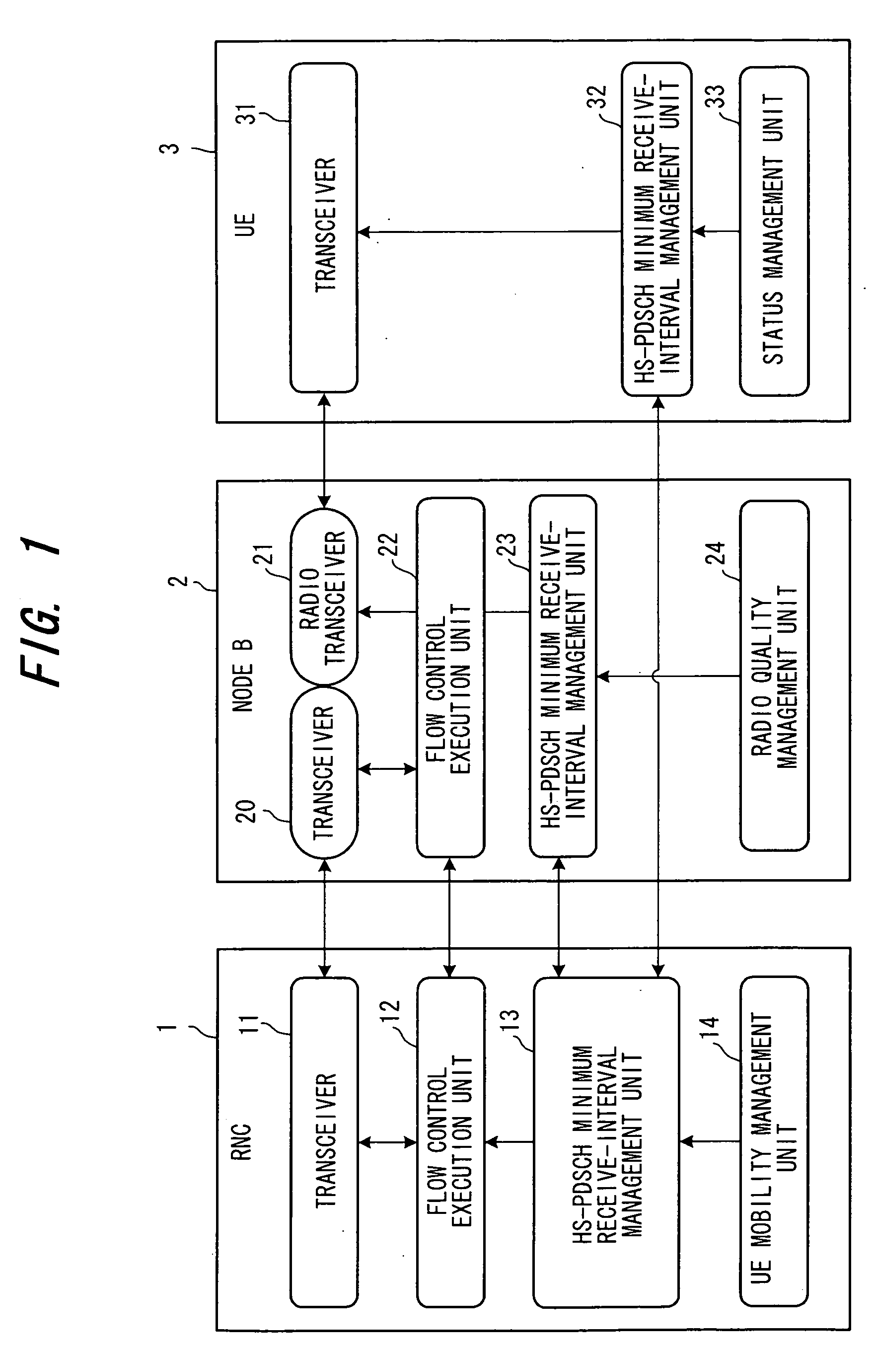
[0073]FIG. 1 is a diagram showing the general configuration of a communication system according to the present invention. The diagram illustrates the functions of nodes and the paths of logical information exchange among these functions.

[0074] Base Station Controller (RNC)

[0075] A base station controller (RNC) 1 is equipped with at least a transceiver 11, a flow control execution unit 12, an HS-PDSCH minimum receive-interval management unit 13 and a UE mobility management unit 14. The transceiver 11 executes processing for sending and receiving packet data to and from a base station 2 based upon flow control.

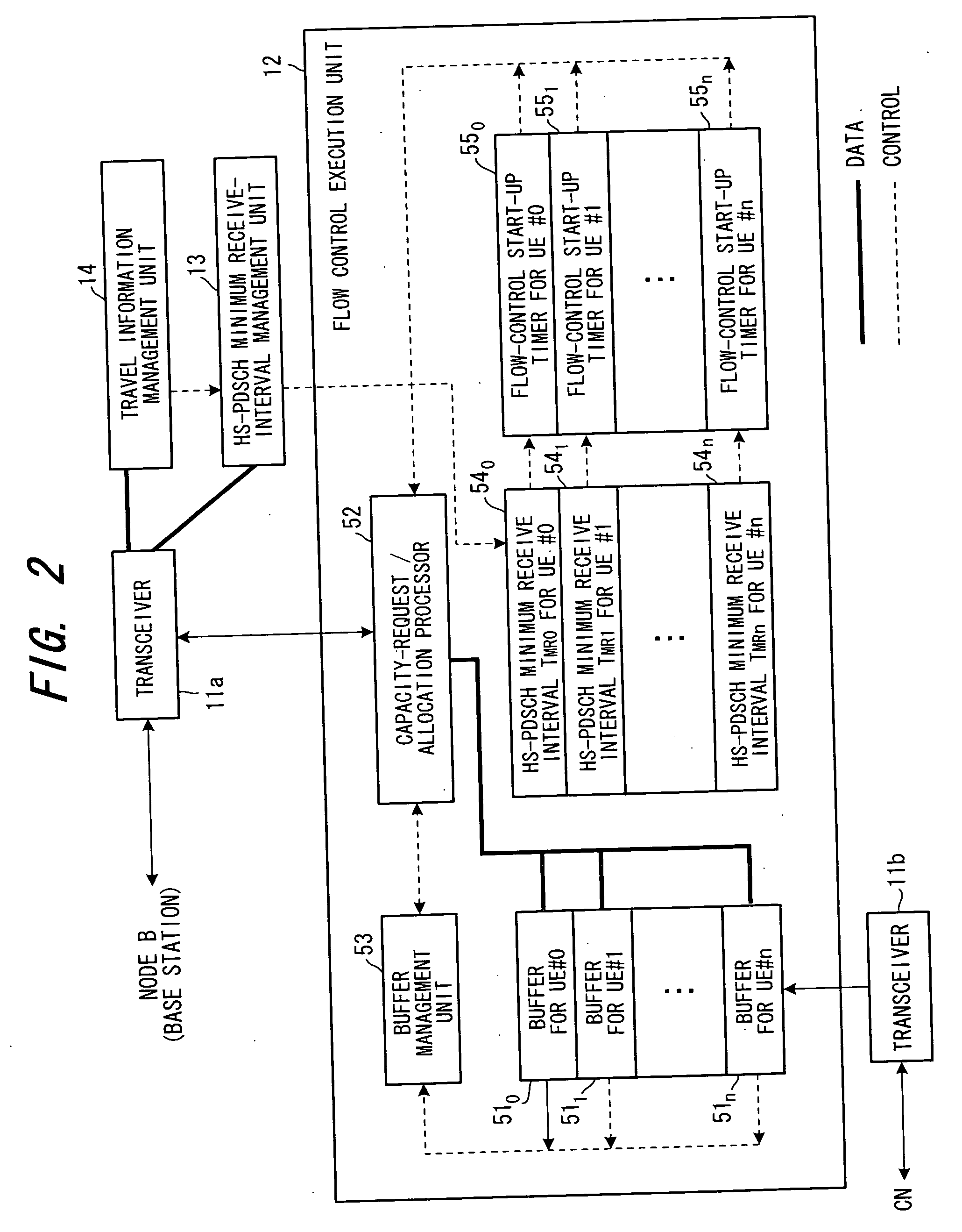
[0076] The flow control execution unit 12 performs flow control between itself and the base station (Node B) 2 on a per-mobile-station basis and exercises control in such a manner that packet data of each mobile station received from a core network (CN) is transmitted to the base station. Flow control refers to control for transmitting ...


PUM


Abstract

Disclosed is a method of controlling flow between a base station controller and a base station in a wireless communication network. The base station controller, base station and a mobile station are provided with the same processing timing that is based upon the minimum receive interval of the mobile station. The base station controller sends and receives a data-transfer request frame and a data-transfer enable frame to and from the base station and performs flow control of data from the base station controller to the base station, and the base station transmits data to the mobile station at the processing timing.

Description

BACKGROUND OF THE INVENTION [0001] This invention relates to a wireless communication network, which includes at least a base station controller (Radio Network Controller: RNC), a base station (Node B) and a mobile station (User Equipment: UE), and to a flow control method. More particularly, the invention relates to wireless communication network and flow control method for performing flow control efficiently by making the processing intervals of flow control, which is implemented between the RNC and Node B, coincide. [0002] (a) HSDPA Wireless Communication System [0003] A wireless communication system that employs the W-CDMA scheme has been standardized by the 3GPP (3rd Generation Partnership Project) and actual service has begun in Japan as well. With 3GPP at the present time, standardization of additional functions is progressing with the aim of providing further functionality. For example, in packet communication, a study of additional functions for raising the communication ra...

Claims


Application Information

Patent Timeline
IPC IPC(8): H04L47/30H04W28/00H04W28/02H04W56/00H04W88/08H04W92/00
CPCH04L47/10H04L47/14H04W88/08H04L47/25H04L47/30H04L47/2441H04W28/02H04W8/04
Inventor IKEDA, EIJIKUMAGAI, TOMONORI
Owner FUJITSU LTD
Learn More