Reduced weight control stage for a high temperature steam turbine

a control stage and high temperature technology, applied in the direction of liquid fuel engines, vessel construction, marine propulsion, etc., can solve the problems of creep damage, creep damage can and does occur in the turbine rotor, and the bucket weight is reduced, so as to reduce subsequent centrifugal loading, reduce the effect of creep strain and the reduction of the weight of the buck

Inactive Publication Date: 2005-10-27
GENERAL ELECTRIC CO
View PDF4 Cites 11 Cited by
  • Summary
  • Abstract
  • Description
  • Claims
  • Application Information

AI Technical Summary

Benefits of technology

[0004] In accordance with a preferred aspect of the present invention, the airfoil of each bucket is provided with an interior cavity thereby reducing the weight of the bucket and subsequent centrifugal loading on the rotor during operation. More particularly, the reduced weight of the bucket reduces the creep strain on the rotor dovetails during long-term centrifugal and high temperature loading on the turbine rotor. Particularly, the interior cavity of the bucket extends through the bucket platform and substantially throughout the entire length of the airfoil, terminating adjacent the airfoil tip. The cavity is closed adjacent the tip of the airfoil and remains open at the platform. The cavity may have a generally airfoil-shaped interior surface corresponding generally to the external profile of the airfoil with due consideration being given to the necessary strength of the airfoil. The cavity may, however, be otherwise shaped. By reducing the weight of the bucket, the long-term creep damage on the rotor dovetail is minimized or eliminated.
[0005] In a preferred embodiment according to the present invention, there is provided a reduced weight control stage for a steam turbine comprising a steam turbine bucket having an airfoil, a platform and a first dovetail for attaching the bucket to a generally correspondingly shaped rotor dovetail, the airfoil having an interior cavity extending between the platform to a location adjacent a tip of the airfoil enabling a reduction in the weight of the bucket for reducing creep damage along the rotor dovetail.

Problems solved by technology

Consequently, steam is emitted over segments of arcs and is therefore not uniformly applied on the first stage bucket airfoils.
Because of this unique non-uniform flow and, hence, loading on the control stage, and over long-term operation at high temperatures, creep damage can and does occur in the turbine rotor, particularly in the coupling between the buckets and the rotor.
The rotor is typically formed of a material which does not have the high creep or rupture strength characteristic of the creep or rupture strength of the buckets end, accordingly, creep damage can and does occur about the rotor dovetails.

Method used


Image

  • Reduced weight control stage for a high temperature steam turbine
  • Reduced weight control stage for a high temperature steam turbine
  • Reduced weight control stage for a high temperature steam turbine

Examples


Embodiment Construction

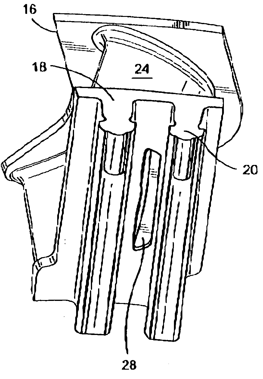
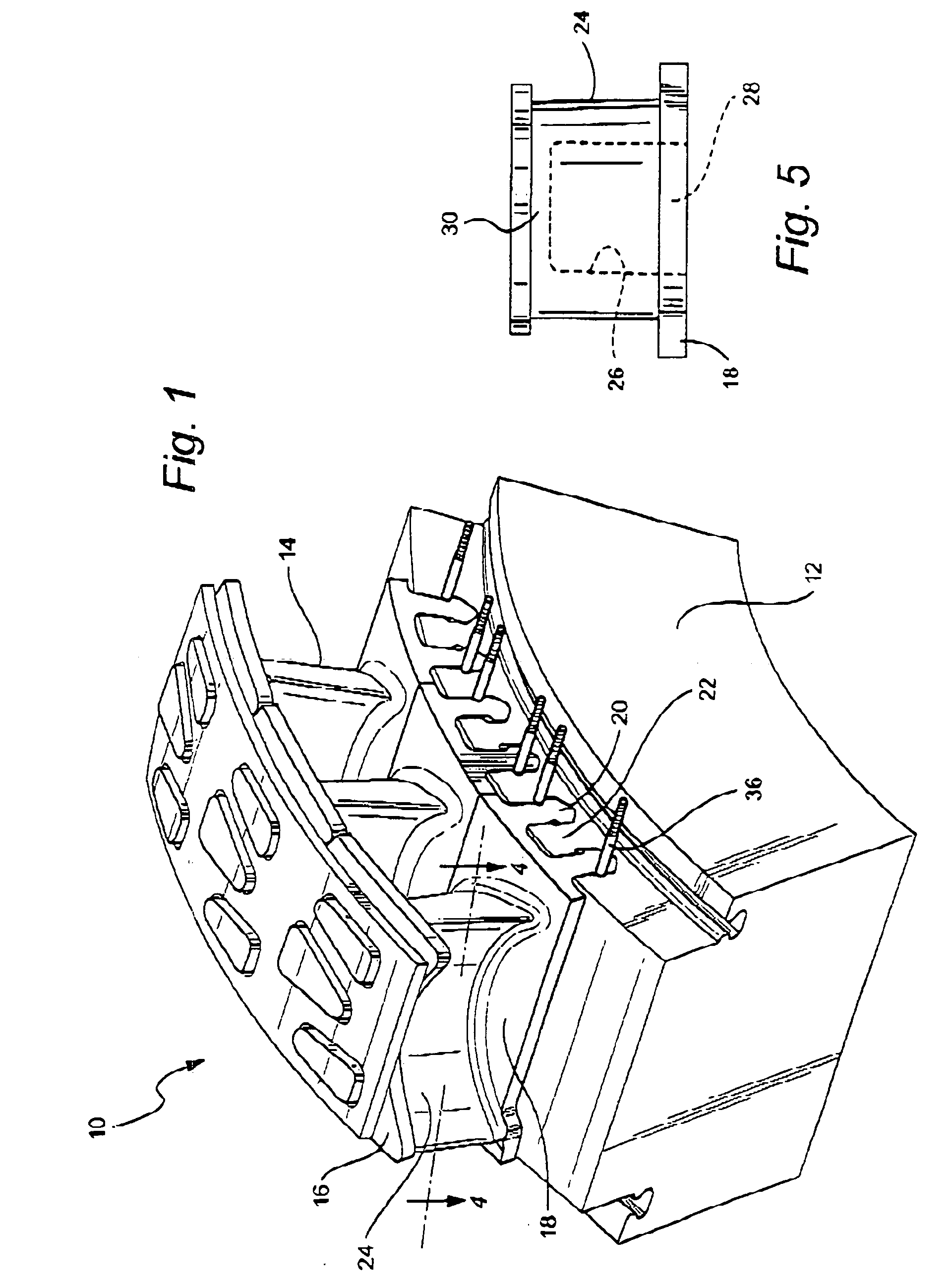
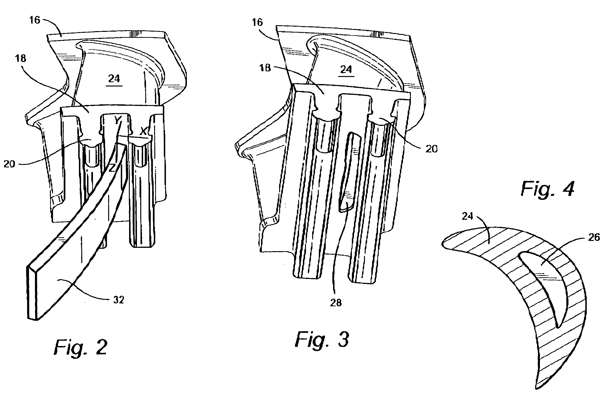
[0012] Referring now to the drawings, particularly to FIG. 1, there is illustrated a portion of a control stage, generally designated 10, for a steam turbine including a rotor 12 and a plurality of buckets 14. Each bucket 14 includes an outer band 16, an inner band or platform 18, one or more and preferably a pair of radially inwardly extending dovetails 20, and an airfoil 24. The dovetails 20 extend axially and are spaced one from the other in a circumferential direction. The rotor 12 includes a plurality of generally correspondingly shaped dovetails 22 which likewise extend in an axial direction. The axially extending dovetails 20 of the buckets 14 are axially inserted onto the rim of the rotor with the dovetails 20 straddling alternate dovetails 22 of the rotor 12. The circumferentially adjacent dovetails 20 of adjacent buckets likewise straddle the adjacent dovetails 22 or the rotor. It will be appreciated that the materials forming the rotor typically have reduced creep or rupt...


PUM


Abstract

The control stage buckets for a steam turbine have airfoils which are hollowed out to form an interior cavity within the airfoil. The cavity opens through the radial inner platform of the bucket and terminates short of the tip of the bucket. The buckets are therefore of reduced weight. This reduced weight causes reduced creep damage in the axially extending dovetails along the rotor rim.

Description

BACKGROUND OF THE INVENTION [0001] The present invention relates to a control stage for a high temperature steam turbine and particularly relates to buckets of the control stage having internal cavities within the airfoils of the buckets to reduce the weight of the bucket and creep damage in the turbine rotor. [0002] The control stage of a steam turbine, i.e., the first stage of the turbine downstream of the control valves and steam inlets, creates unique loading on the control stage buckets. Typically, there are four inlets for admitting steam to the control stage, with a control valve for each inlet. The inlets are generally arranged in quadrants. Consequently, steam is emitted over segments of arcs and is therefore not uniformly applied on the first stage bucket airfoils. Because of this unique non-uniform flow and, hence, loading on the control stage, and over long-term operation at high temperatures, creep damage can and does occur in the turbine rotor, particularly in the coup...

Claims


Application Information

Patent Timeline
Patent Type & Authority Applications(United States)
IPC IPC(8): F01D5/18F01D5/30
CPCF01D5/18F05D2220/31F05D2240/81F05D2230/12F05D2230/11
Inventor DAUSACKER, PAUL WALTERDEALLENBACH, ROBERT EDWARDHOLLIDAY, ALLYN KEITH
Owner GENERAL ELECTRIC CO
Why Eureka
Try Eureka