
Automatic balancing apparatus and rotative apparatus using the same

a rotative apparatus and automatic balancing technology, applied in the field of automatic balancing apparatus, can solve the problems of difficult to ensure difficult to considerably improve the balance of disc rotation, and difficult to return magnetic fluid to or hold by the ring magnet, so as to achieve the effect of improving the balance of rotation of the automatic balancing apparatus

Inactive Publication Date: 2005-10-20
SONY CORP
View PDF5 Cites 5 Cited by
  • Summary
  • Abstract
  • Description
  • Claims
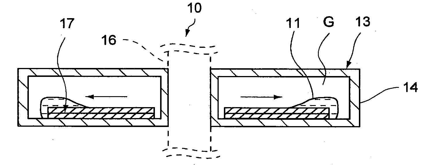
  • Application Information

AI Technical Summary

Benefits of technology

[0010] In the automatic balancing apparatus according to a preferred embodiment of the present invention, the magnet is provided to extend from the central side to the outer circumferential side of the housing member. Accordingly, when the automatic balancing apparatus starts rotating in vertical attitude, for example, even if the balancer accumulates in the bottom section of the housing member, magnetic force can be made to act on the balancer from the vicinity thereof, whereby the balancer can be reliably returned to and held by the magnet irrespective of the attitude of the automatic balancing apparatus. Accordingly, the automatic balancing apparatus can start rotating with the balancer held by the magnet irrespective of the attitude of the automatic balancing apparatus, whereby the balance of rotation can be improved in a stable manner. In addition, the magnet has a flat shape. Accordingly, even if the magnet is provided in the inside of the housing member, the amount of the balancer can be ensured by decreasing the thickness of the magnet in the axial direction of rotation of the housing member.
[0017] As described above, at the starting time of rotation of the automatic balancing apparatus, the automatic balancing apparatus can be rotated in such a manner that the balancer accumulated on the outer circumferential side of the housing member is returned to and held by magnetic force irrespective of the attitude of the automatic balancing apparatus, whereby the balance of rotation of the automatic balancing apparatus can be improved in a stable manner.

Problems solved by technology

However, in the art disclosed in Patent Document 1, when a disc drive is positioned in vertical attitude, i.e., the recording surface of a disc is positioned at right angles to the ground, the distance between the ring magnet and the magnetic fluid accumulated in the bottom section of the disc-shaped member is large, so that the magnetic fluid cannot easily be returned to or held by the ring magnet.
This leads to the problem that when the disc drive is positioned in certain attitudes, it is difficult to ensure the balance of rotation of the disc.
In addition, there is the problem that when the magnetic fluid moves by centrifugal force in a direction approximately opposite to the direction in which the rotation center of the disc deviates, the magnetic fluid flows along the outer circumference of the disc-shaped member and the deviation of the magnetic fluid disappears, so that the balance of rotation is difficult to considerably improve with a small amplitude of vibration.

Method used


Image

  • Automatic balancing apparatus and rotative apparatus using the same
  • Automatic balancing apparatus and rotative apparatus using the same
  • Automatic balancing apparatus and rotative apparatus using the same

Examples


Embodiment Construction

[0032] Preferred embodiments of the present invention will be described below with reference to the accompanying drawings.

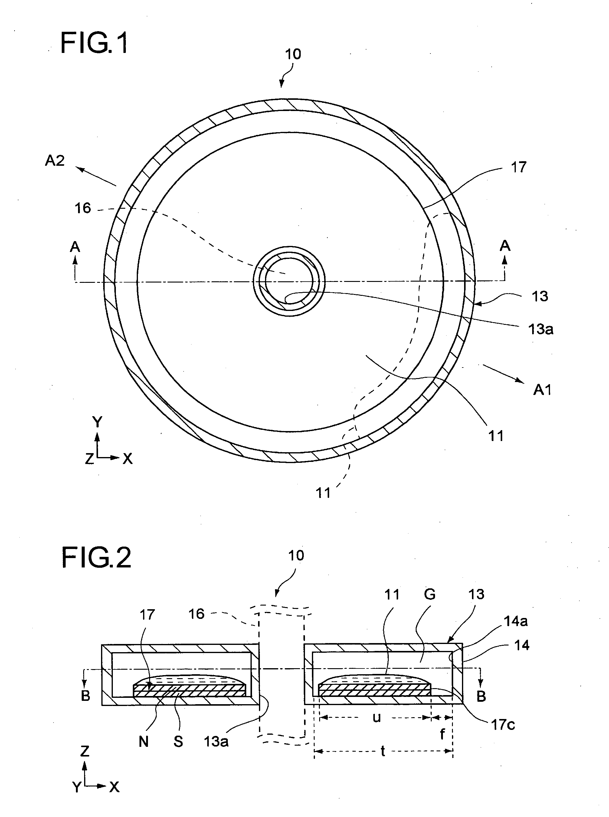
[0033]FIGS. 1 and 2 represent, respectively, horizontal and vertical cross-sectional views showing an automatic balancing apparatus according to a first preferred embodiment of the present invention. FIG. 3 is a vertical cross-sectional view showing a disc rotation apparatus according to a preferred embodiment of the present invention.

[0034] An automatic balancing apparatus 10 according to the first preferred embodiment includes a balancer 11 made of a magnetic fluid, a flat disk-shaped magnet 17 having a hole at its center, and a disk-shaped housing member 13 having an internal space G in which the balancer 11 and the magnet 17 are housed.

[0035] A through-hole 13a through which a rotation shaft 16 of a motor 61 shown in FIG. 3 is provided in the housing member 13 is provided at the center of the housing member 13. The constituent material of the housing membe...


PUM

PropertyMeasurementUnit
rotationaaaaaaaaaa
stabilityaaaaaaaaaa
rotation speedaaaaaaaaaa

Abstract

An automatic balancing apparatus includes a balancer made of a magnetic fluid, a housing member rotatably provided and for housing the balancer, and a flat magnet disposed integrally rotatable within the housing member and to extend from a center of rotation to an outer circumferential side of the housing member. Accordingly, the automatic balancing apparatus can start rotating with the balancer held by the magnet irrespective of the attitude of the automatic balancing apparatus, whereby the balance of rotation can be improved in a stable manner.

Description

CROSS REFERENCE TO RELATED APPLICATONS [0001] The present invention contains subject matter related to Japanese Patent Application JP2004-123174, filed to the Japanese Patent Office on Apr. 19, 2004, the entire content of which being incorporated herein by reference. BACKGROUND OF THE INVENTION [0002] 1. Field of the Invention [0003] The present invention relates to an automatic balancing apparatus for maintaining balance of rotation, and a rotative apparatus equipped with the automatic balancing apparatus. [0004] 2. Description of Related Art [0005] In recent years, it has been known that in a disc drive such as an optical disc drive or a magnetic disc drive for recording and reproducing data, rotation of the disc becomes unbalanced during rotation of the disc on a turntable, so that the stability of recording and reproduction decreases. [0006] Technology has been disclosed for improving the balance of rotation of discs, in which a disc-shaped member having a space or chamber in wh...

Claims


Application Information

Patent Timeline
Patent Type & Authority Applications(United States)
IPC IPC(8): F16F15/34G01M1/16G01M1/32G11B17/028G11B17/03F16F15/32G11B19/20G11B33/08H02K7/04
CPCG01M1/323G11B33/08G11B19/2027G11B19/2009G11B19/20G11B17/02
Inventor SHISHIDO, YUJI
Owner SONY CORP
Learn More