Finisher and image forming apparatus equipped therewith

Active Publication Date: 2005-10-20
KONICA MINOLTA BUSINESS TECH INC
View PDF6 Cites 14 Cited by
  • Summary
  • Abstract
  • Description
  • Claims
  • Application Information

AI Technical Summary

Benefits of technology

[0008] The purpose of the present invention is to provide a sheet finisher with a simple configuration and to provide an image forming apparatus in which improvement in the booklet quality is achieved in a cutting device that cuts the edge of booklets that are transported after center-folding, by stabilizing the booklet transportation and by making highly accurate the dimensions of cutting the booklet whose edges are cut.
[0021] As has been described above, it is possible to obtain the following effects from the sheet finisher and image forming apparatus according to the present invention.
[0022] Using the finisher and image forming apparatus according to the present invention it is possible to cut the appropriate amount suitable for different sheet sizes for each booklet and to prepare high quality booklets with relatively simple controls.

Problems solved by technology

Further, in this cutting method, since the amount of movement to be made by moving the leading edge stopper by driving the first driving means to the specific location depending on the sheet size and number of sheets of paper and the amount of movement of the booklet to make the front end part of the booklet push against the leading edge stopper by driving the second transporting means using the second drive means, and the amount of movement of the pressing means that presses the top surface of the booklet are all set individually and since they are all carried out by different driving means, there is the problem that the apparatus becomes complex and also the-control of the timings of these plural driving means becomes difficult.

Method used


Image

  • Finisher and image forming apparatus equipped therewith
  • Finisher and image forming apparatus equipped therewith
  • Finisher and image forming apparatus equipped therewith

Examples


Embodiment Construction

[0049] The sheet finisher according to the present invention is described in detail in the following while referring to the drawings. Furthermore, it is to be understood that the sheet finisher according to the present invention shall not be limited to the following preferred embodiment alone.

[0050] (Sheet Finisher)

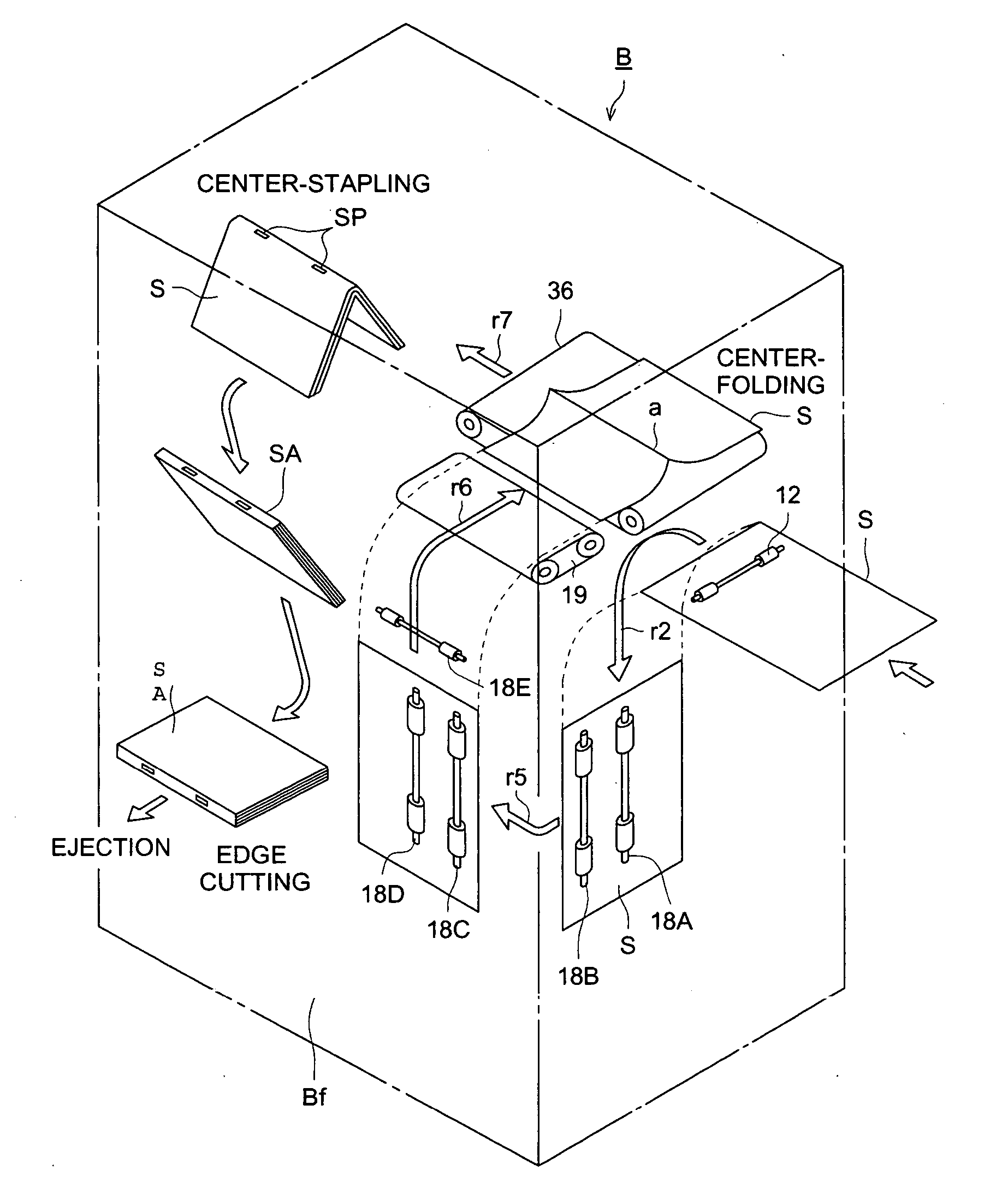
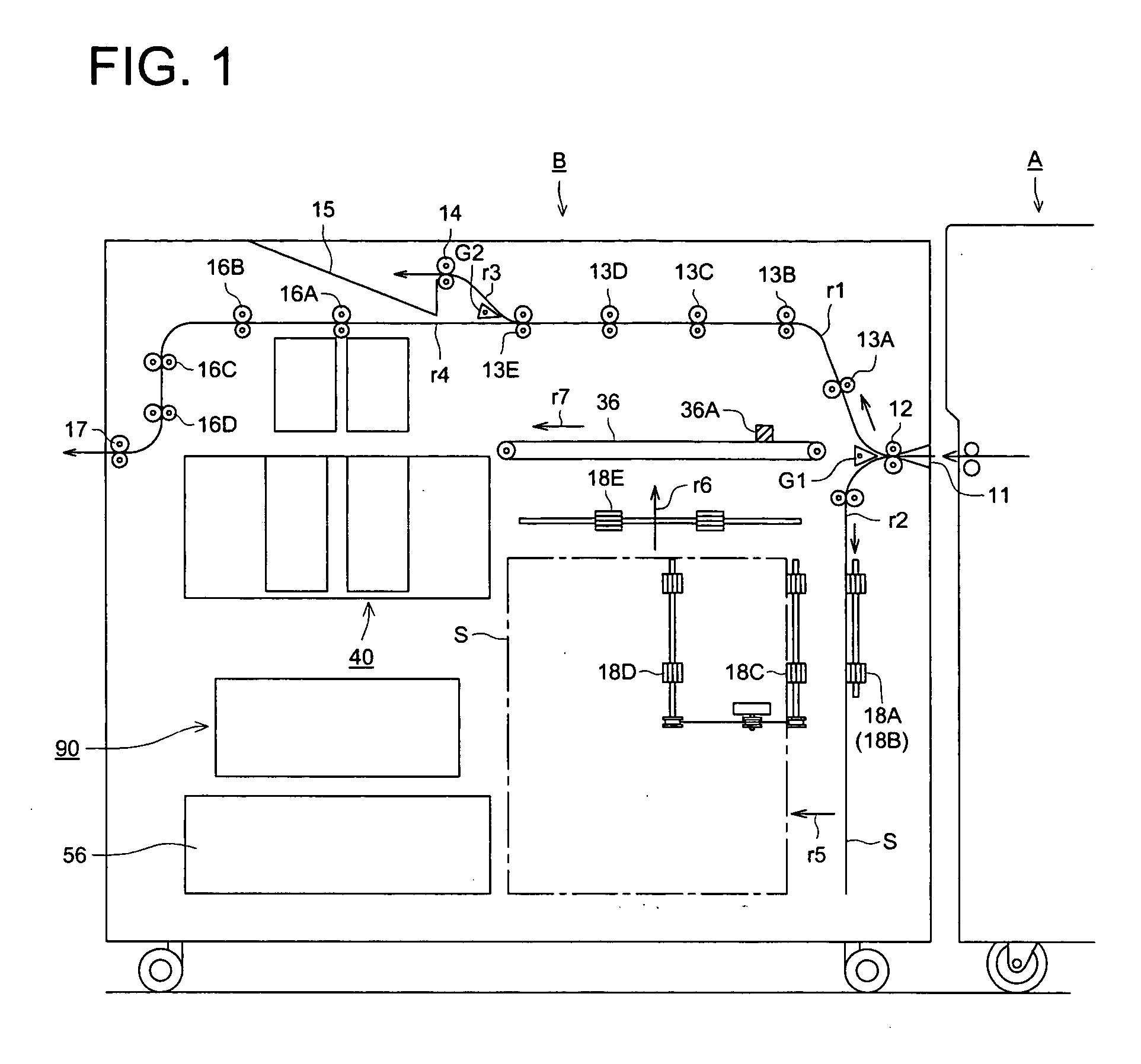
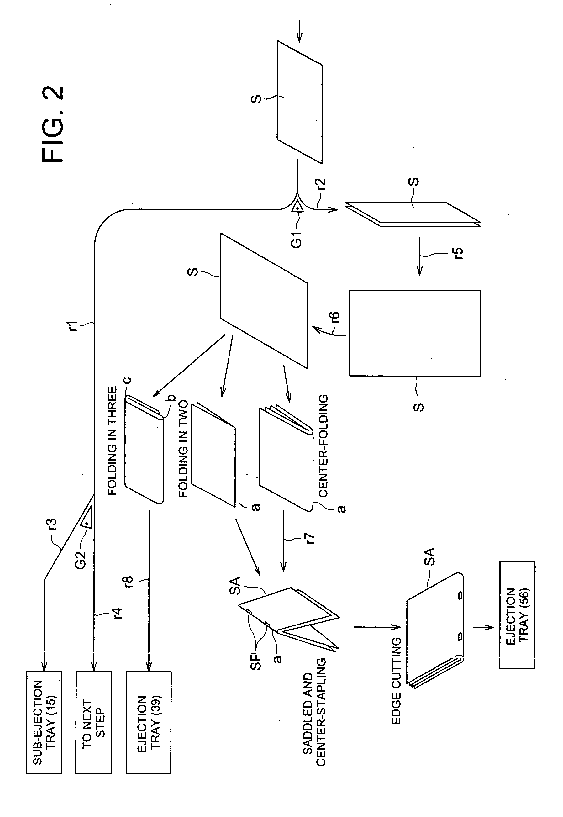
[0051]FIG. 1 is a schematic diagram showing the sheet transport during the center-folding and center-stapling processes of the sheet finisher B, FIG. 2 is a schematic diagram showing the sheet transport process of the sheet finisher B, FIG. 3 is the front view of the finisher B, FIG. 4 is the right side view and FIG. 5 is the left side view.

[0052] As is shown in FIG. 1, the sheet finisher B has been installed in the image processing apparatus A, the sheet on which image has been recorded in the image recording section of the image forming apparatus A is transported to the sheet finisher B which carries out finishing of the sheet.

[0053] Firstly, the sheet transporting ...


PUM

PropertyMeasurementUnit
Thicknessaaaaaaaaaa
Pressureaaaaaaaaaa
Sizeaaaaaaaaaa

Abstract

A finisher for finishing a booklet having a bundle of center-folded sheets, includes: a detector for detecting an end on a side of a folded portion of the booklet: a moving device for conveying the booklet by movement thereof; a controller for controlling the movement of the moving device; and a cutting device for cutting an edge on a side opposite to the end of the booklet, which has been conveyed by the moving device to a cutting position. The controller controls the movement of the moving device from a position where the detector has detected the end of the folded portion to the cutting position so that a size of a booklet after being cut is kept constant for each of sheet sizes.

Description

[0001] The present invention relates to a finisher that-cuts the edges of a booklet prepared by center-folding the sheets and binds the booklet, and to image forming apparatus containing such a sheet finisher. BACKGROUND OF THE INVENTION [0002] Conventionally, a finisher that comprises a cutting device that cuts and aligns the edges of booklet prepared by center-stapling and center folding have been realized in the printing industry. [0003] Further, in recent years, sheet finishers have been proposed that accept sheets on which images have been formed by an image forming apparatus such as copiers, printers, etc., carries out center-stapling and center-folding processes on them to bind into a booklet like a weekly magazine, and which comprise a cutting device that thereafter cuts and aligns the edges of the booklet. [0004] The cutting device disclosed in Patent Document 1 (representing Japanese Patent Application Laid Open No. 2000-198613) is one in which the booklet after center-sta...

Claims


Application Information

Patent Timeline
IPC IPC(8): B42B2/00B42C1/12B65H35/06G03G15/00
CPCB42C1/12B65H35/06B65H2301/4505B65H2511/222B65H2511/514B65H2701/13214Y10S83/934G03G15/6582G03G2215/00814B65H2701/1932B65H2220/02B65H2220/01B65H45/18B65H2701/1829Y10T83/9493
Inventor KAWATSU, KENJISHIDA, TOSHIOWAKABAYASHI, HIROYUKIUCHIYAMA, MASAAKIHATTORI, MASATO
Owner KONICA MINOLTA BUSINESS TECH INC
Why Eureka
Try Eureka