
Method and control system for positioning a crankshaft of an internal combustion engine

a technology of internal combustion engine and control system, which is applied in the direction of electric control, engine starters, machines/engines, etc., can solve the problems of large relative deviation and inability to achieve field-oriented motor regulation

Active Publication Date: 2005-10-20
CONTI TEMIC MICROELECTRONIC GMBH
View PDF16 Cites 29 Cited by
  • Summary
  • Abstract
  • Description
  • Claims
  • Application Information

AI Technical Summary

Benefits of technology

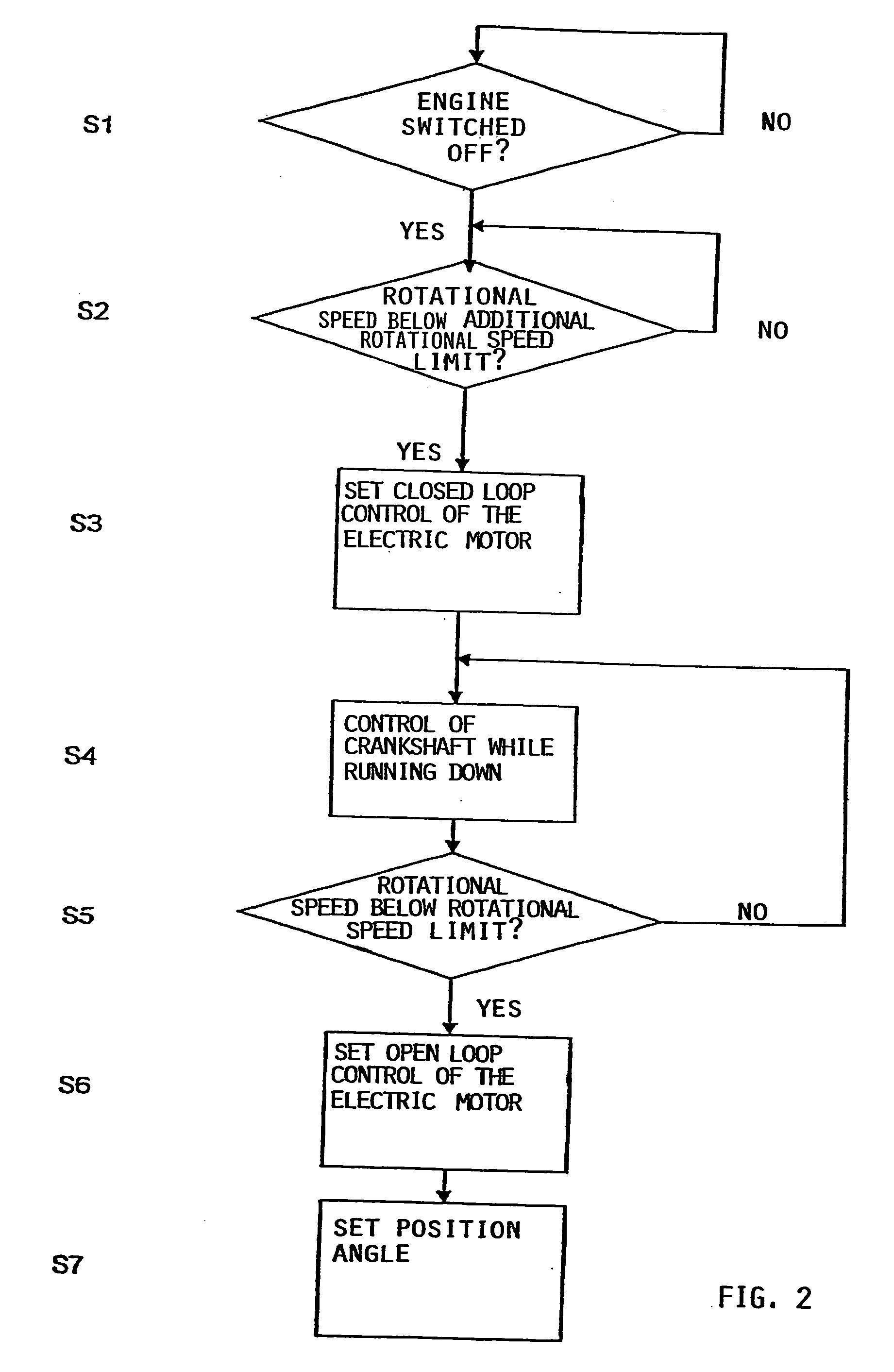
[0015] The use of the open loop control mode for the electric motor also has the advantage that the electric motor is operated independently of the rotational speed detected for the crankshaft. This is made possible by operating the electric motor with a specific drive frequency and with a specific voltage or current in order to reach a prespecified torque. The electric motor can thus be operated in such a way as to allow the position angle to be set. The current or voltage and frequency are selected so as to ensure that the torque that is reached is sufficient to prevent the internal combustion engine from reversing. This has the advantage of also enabling position / rotational speed sensors which do not recognise left / right rotation to determine the precise position of the internal combustion engine.

Problems solved by technology

Particularly with very low rotational speeds, such as those which occur when the crankshaft of the internal combustion engine runs down shortly before the crankshaft comes to a standstill, the degree of imprecision for determining the rotational speed may result in a very large relative deviation, so that field-oriented motor regulation is no longer possible without significant running problems occurring while the electric motor is in operation.

Method used


Image

  • Method and control system for positioning a crankshaft of an internal combustion engine
  • Method and control system for positioning a crankshaft of an internal combustion engine
  • Method and control system for positioning a crankshaft of an internal combustion engine

Examples


Embodiment Construction

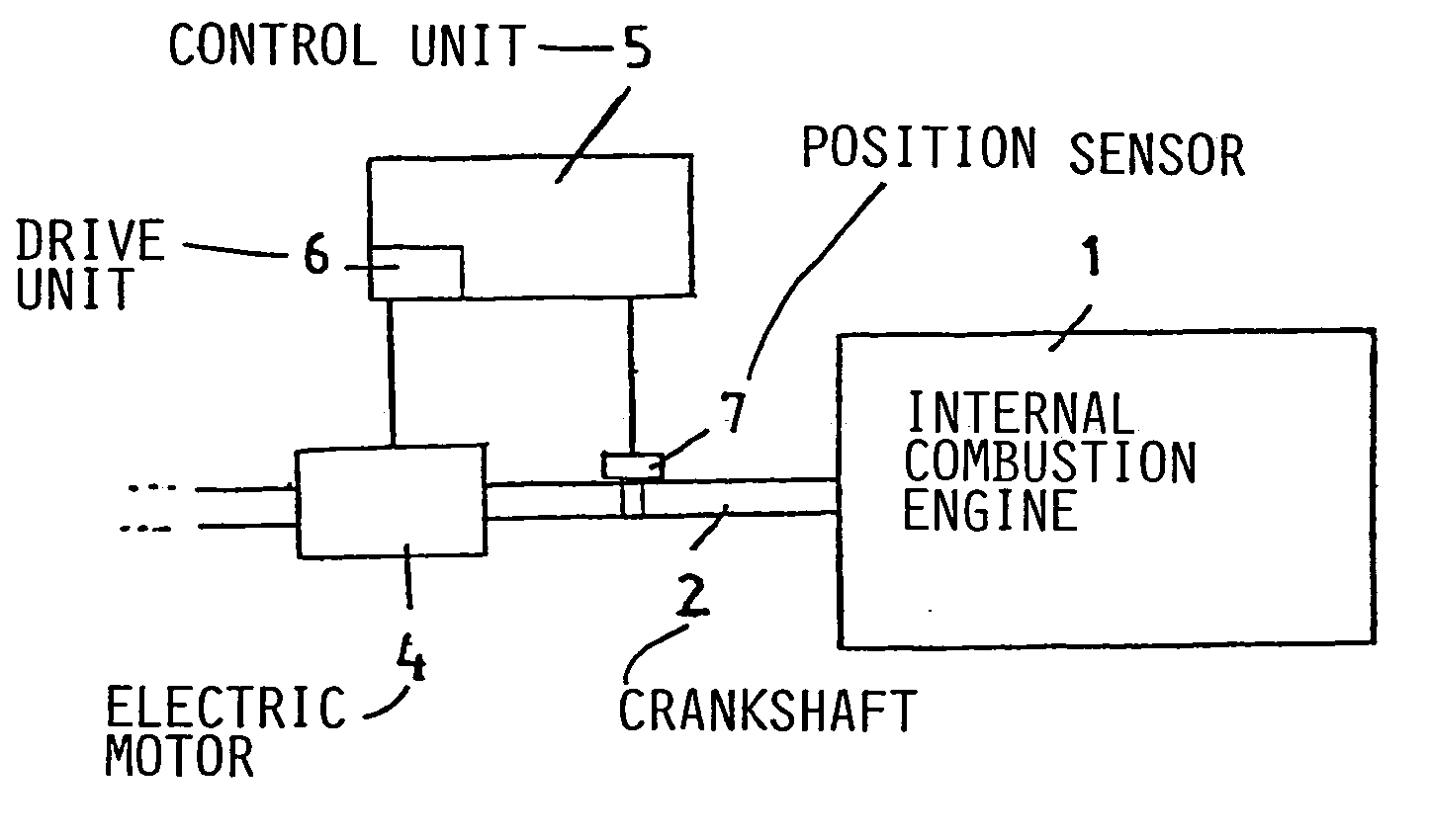
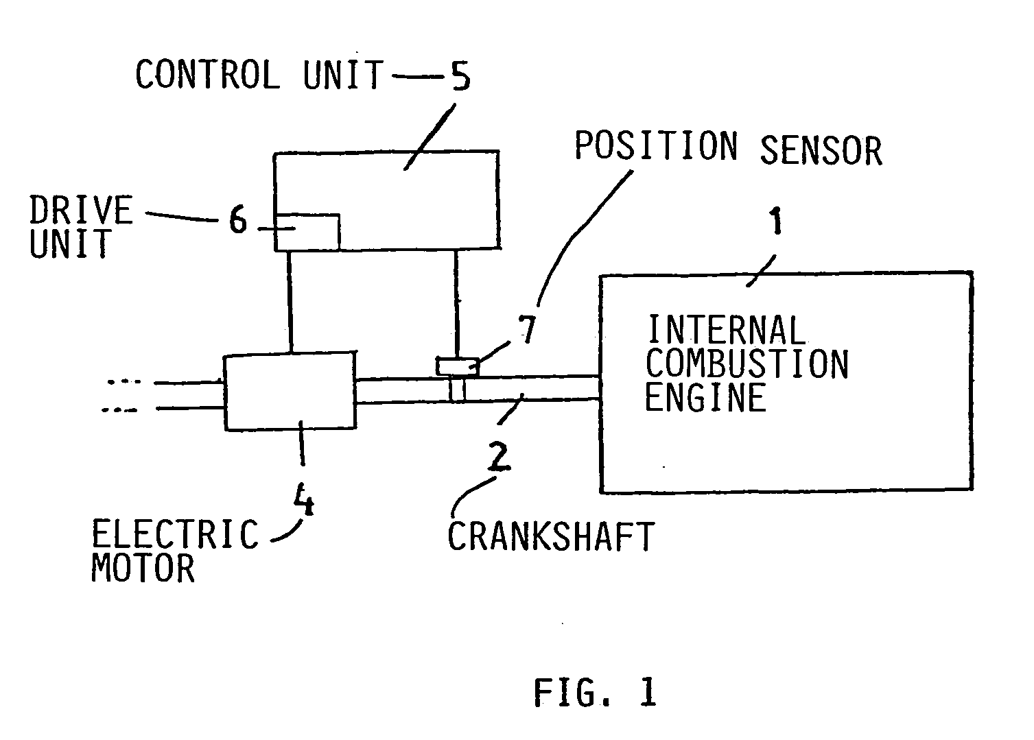
[0020]FIG. 1 shows an engine system, e.g. for a motor vehicle. It comprises e.g. a four-cylinder internal combustion engine 1 working in a four-stroke cycle, which transfers the torques to further components (not shown) of a drive system for the vehicle and onto the drive wheels of the motor vehicle via a crankshaft 2.

[0021] In this exemplary embodiment, an electric motor 4, which acts as a starter / generator, is positioned directly on the crankshaft 2. The electric motor 4 comprises a rotor (not shown) which is firmly connected to the crankshaft 2 and a stator (not shown) which rests e.g. on the housing of the internal combustion engine 1. In the exemplary embodiment shown, the electric motor 4 is an asynchronous motor 4, but it can also be a synchronous motor or similar.

[0022] An electric motor 4 of this type has a high torque for operating as a starter. In other embodiments of the invention (not shown), the electric motor 4 is coupled with the crankshaft 2 via a transmission gea...


PUM


Abstract

The invention relates to a method and a control system for driving an electric motor (4) coupled with a crankshaft (2) of an internal combustion engine, in order to position the crankshaft (2) at a starting angle, wherein the control system comprises: a detection device (7) for receiving and / or determining a position angle and / or the rotational speed of the crankshaft (2), and a control unit (5) which is capable of driving the electric motor (4) in a closed loop control mode dependent on the rotational speed of the crankshaft and of positioning the crankshaft (2) at said starting angle after the internal combustion engine (1) is stopped, so that, in the case of a subsequent start, the internal combustion engine (1) is started from this starting angle, wherein the control unit (5) is designed so as to drive the electric motor (4) according to an open loop control mode, below a prespecified rotational speed limit independently of the rotational speed in an open loop control, so that the crankshaft (2) is set to the starting angle.

Description

PRIORITY CLAIM [0001] The priority of EP 04 009 028.4 filed Apr. 15, 2004 is claimed and the disclosure thereof is incorporated herein by reference. FIELD OF THE INVENTION [0002] The invention relates to a method and a control system for positioning a crankshaft of an internal combustion engine. BACKGROUND TO THE INVENTION [0003] In order to start up internal combustion engines, it is necessary to use a starter, e.g. in the form of an electric motor which is directly or indirectly coupled with the crankshaft of the internal combustion engine. The crankshaft is then accelerated by the starter until it reaches the engine speed required to start the internal combustion engine. [0004] The starting torque which the starter initially needs to generate varies according to the position angle of the crankshaft. Particularly when a cylinder is in a compression stroke at that point, a high starting torque is required which has a negative impact on the starting behaviour of the internal combust...

Claims


Application Information

Patent Timeline
IPC IPC(8): F02D41/04F02D41/34F02N11/06F02N11/08F02N99/00
CPCF02D41/009F02D41/042F02D2041/0095F02N2019/008F02N11/0814F02N11/0859F02N19/005F02N11/06
Inventor HOEVERMANN, MARKUS
Owner CONTI TEMIC MICROELECTRONIC GMBH
Learn More