
Air-conditioning control unit

a technology of air-conditioning control unit and control unit, which is applied in the direction of domestic cooling apparatus, lighting and heating apparatus, heating types, etc., can solve the problems of increased manufacturing cost and complex structure of the system, and achieve the effect of reducing the difference between blowing temperature, improving comfortability during heating operation, and reducing the differen

Inactive Publication Date: 2005-10-20
CALSONIC KANSEI CORP
View PDF4 Cites 17 Cited by
  • Summary
  • Abstract
  • Description
  • Claims
  • Application Information

AI Technical Summary

Benefits of technology

The present invention provides an air-conditioning control unit for vehicles that can better control the temperature of the air in the vehicle and reduce manufacturing costs. The control unit includes a refrigerant circuit, indoor heat exchangers, and an airflow distributing door that controls the distribution of air. The control unit can switch between a cooling operation and a heating operation mode by controlling the airflow distributing door. The control unit can also control the airflow distributing door to increase or decrease the amount of adjusting air in specific air passages during cooling or heating operation modes. This helps to accurately control the air temperature and improve comfort for the vehicle occupants.

Problems solved by technology

However, in the case where no heat source of the engine exists, as in the electric vehicle by fuel cell, since the air conditioning system is required another heat source, structure and control of the system becomes complex and manufacturing cost thereof is raised.

Method used


Image

  • Air-conditioning control unit
  • Air-conditioning control unit
  • Air-conditioning control unit

Examples


Embodiment Construction

[0027] There will be detailed below the preferred embodiments of the present invention with reference to the accompanying drawings. Like members are designated by like reference characters.

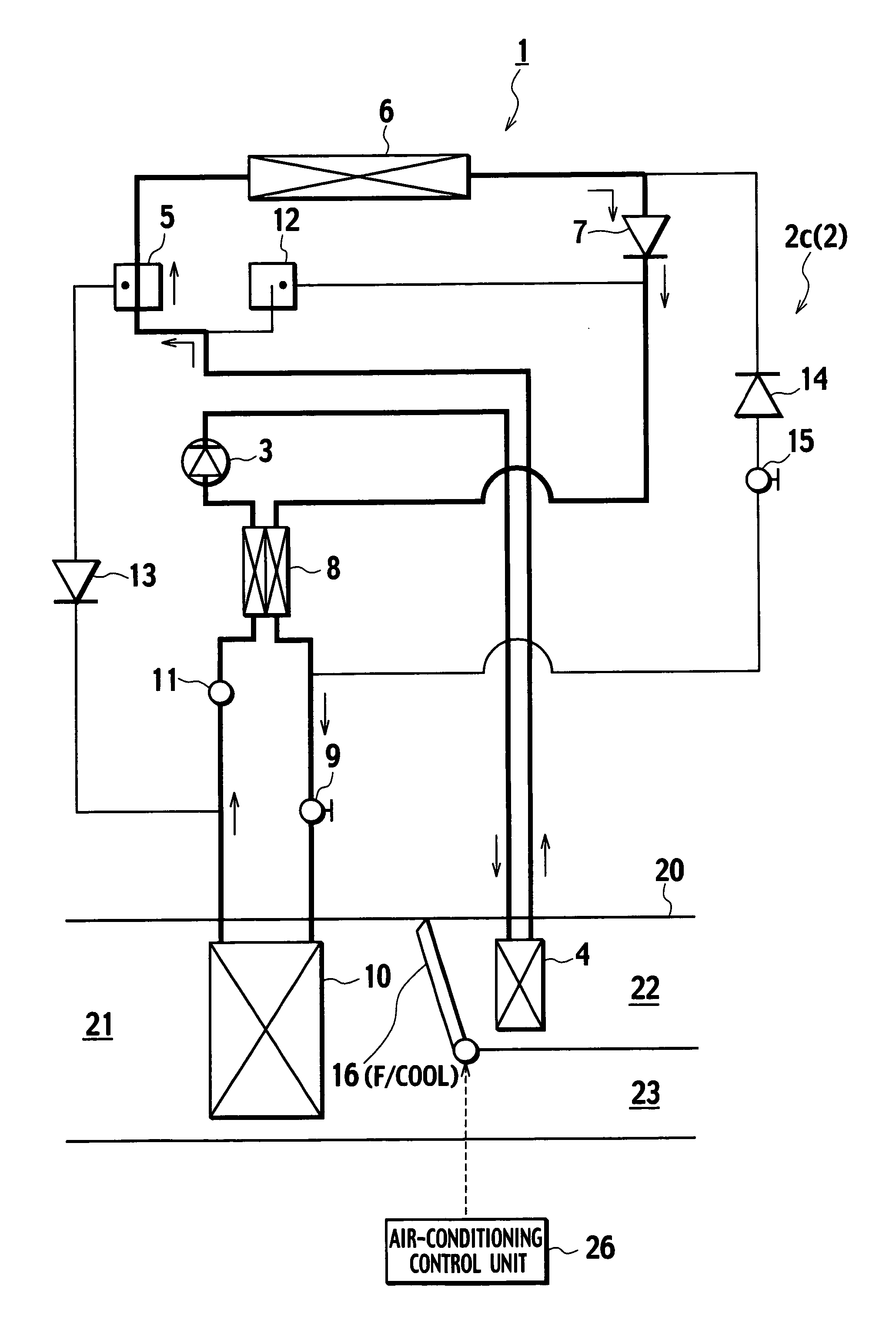
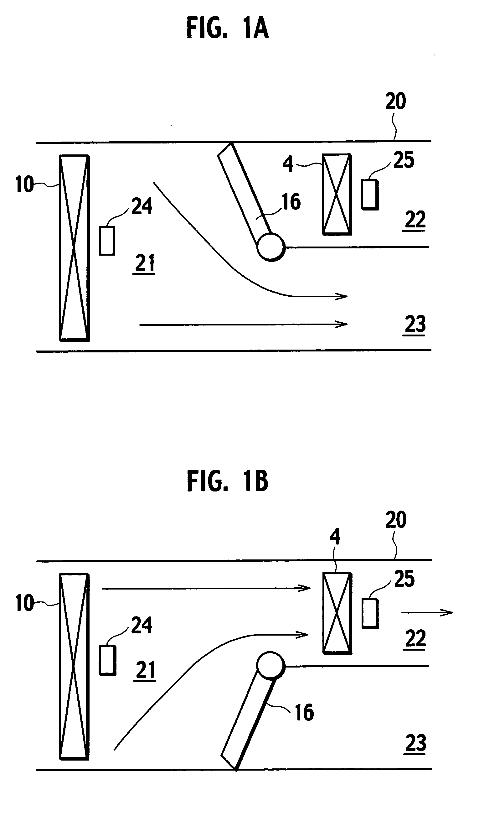
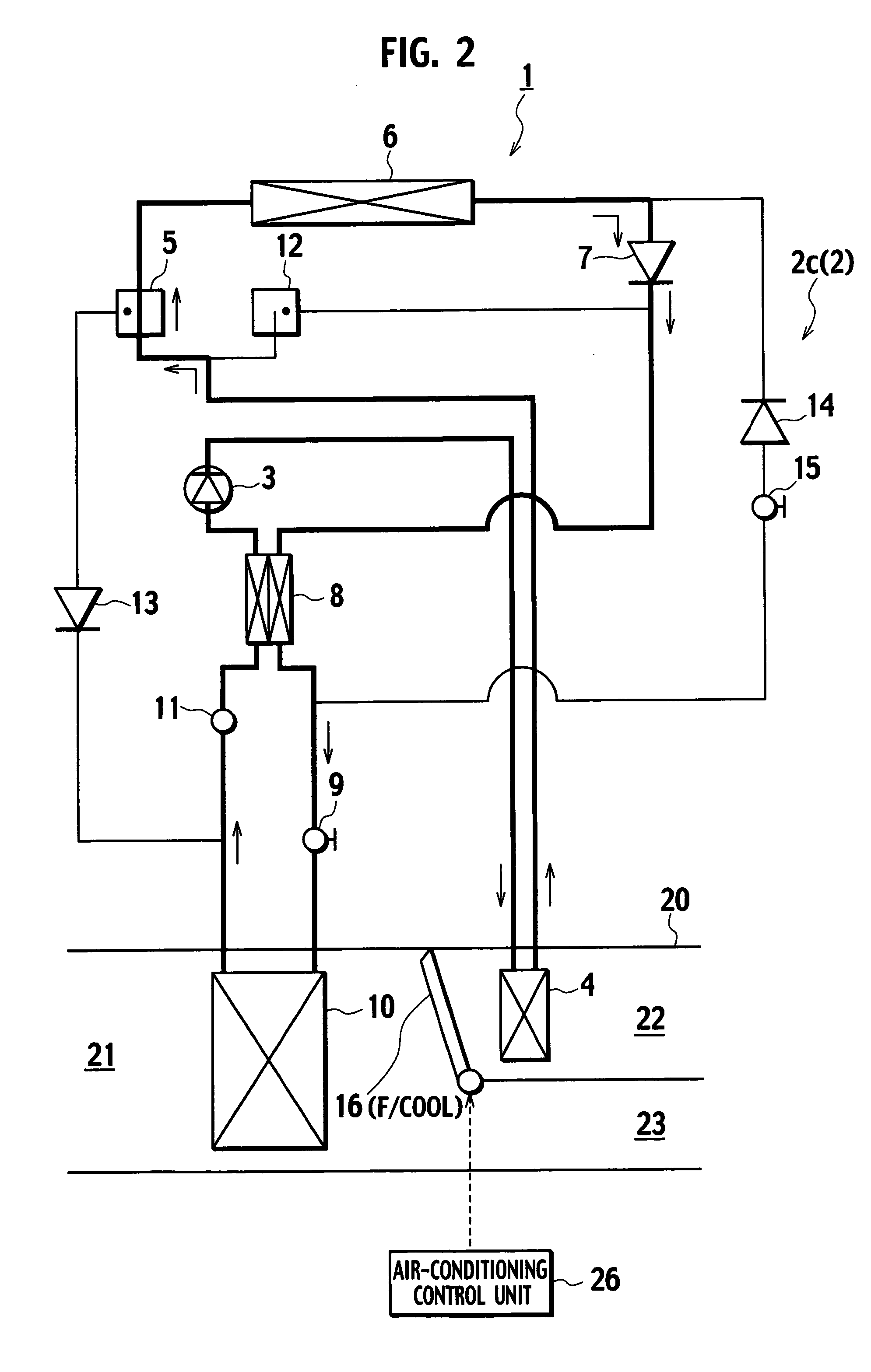
[0028]FIGS. 1A and 1B show a first embodiment of the present invention. The drawings show an arrangement of a first air passage 21 which are divided by a wall into a second air passage 22 and a third air passage 23 in a duct 20. There is provided with a first indoor heat exchanger 10 in the first air passage 21, and with a second indoor heat exchanger 4 in the second air passage 22. Furthermore, at the end of the wall which is located between the second air passage 22 and the third air passage 23, there is provided with a airflow distribution door 16 which is swungly controlled by an air-conditioning unit 26 according to the present invention.

[0029] In the above described arrangement shown in FIGS. 1A and 1B, air passes through the first indoor heat exchanger 10 (at low temperate) and airflow fl...


PUM


Abstract

An air-conditioning control unit (26) controls the airflow distributing door (16), a first indoor heat exchanger (10) is provided in the first air passage (21) and a second indoor heat exchanger (4) is provided in the second air passage (22). in adjusting air sent from the first air passage (21) is distributed into the second air passage (22) and the third air passage (23) by controlling the airflow distributing door (16). In switching from the cooling operation state to the heating operation state, the flow of the adjusting air in the second air passage (22) is increased by controlling the airflow distributing door (16) by the air-conditioning control unit (26) prior to the switching of refrigerant circuit from the cooling control mode to the heating control mode.

Description

BACKGROUND OF THE INVENTION [0001] 1. Field of the Invention [0002] The present invention relates to an air-conditioning control unit used for an air conditioning system that performs heating operation using a refrigerant of a fuel car, electric car or the like as a heat source. [0003] 2. Description of the Related Art [0004] A Well-known conventional air conditioning system adjusts temperature of air in a cabin by mixing hot air from a heat exchanger of a radiator for an engine as a heat source and cold air from a cooler using refrigerant as disclosed in a patent brochure, Japanese Patent Application Laid-Open No. 2002-274147. [0005] In the case where cooling water in the radiator for the engine is used as a beat source, the above described conventional air conditioning system would be effective to control the temperature of air in the cabin. [0006] However, in the case where no heat source of the engine exists, as in the electric vehicle by fuel cell, since the air conditioning sy...

Claims


Application Information

Patent Timeline
Patent Type & Authority Applications(United States)
IPC IPC(8): B60H1/22B60H1/00F24F11/08F25B40/00F25B41/04F25D17/04
CPCB60H1/00792B60H1/00835B60H1/00921F25B2600/2507F25B40/00F25B41/04F25B2400/0409F24F11/08F24F11/30F25B41/20F25B41/24
Inventor NAKAMURA, KOJIRO
Owner CALSONIC KANSEI CORP
Learn More