
Toolless adjustable base for a portable saw

a portable saw and adjustable technology, applied in the direction of metal sawing equipment, sawing equipment, milling equipment, etc., can solve the problems of inconvenient use, limited torque that the user can apply, and non-secure attachment of the base to the power tool

Active Publication Date: 2005-10-20
ONE WORLD TECH +1
View PDF22 Cites 34 Cited by
  • Summary
  • Abstract
  • Description
  • Claims
  • Application Information

AI Technical Summary

Benefits of technology

[0008] A goal of the present invention is to provide a toolless adjustable base for a portable saw that is convenient to a user by providing both sufficient clearance to adjust the base and sufficient torque to reattach the base relative to the tool while minimizing the effort and the range of motion required by the user.

Problems solved by technology

However, the use of a fastener may require utilization of a separate tool which may be inconvenient to a user.
Alternatively, prior art adjustable bases may include a threaded fastener with a knob formed thereon, yet compactness may limit the size of the knob thus limiting the torque that may be applied by the user which may result in a non-secure attachment of the base to the power tool.
Accordingly, such prior art adjustable bases that utilize a threaded member typically permit less than a half turn of the lever thus limiting the range of torque provided to secure the base to the tool and / or limiting the amount of clearance provided to adjust the base relative to the tool.
Some offset lobe clamp member designs may be inconvenient to the user, by requiring removal of a baseplate from the adjustable base before the lever can be fully rotated to the unlock position.

Method used


Image

  • Toolless adjustable base for a portable saw
  • Toolless adjustable base for a portable saw
  • Toolless adjustable base for a portable saw

Examples


Embodiment Construction

)

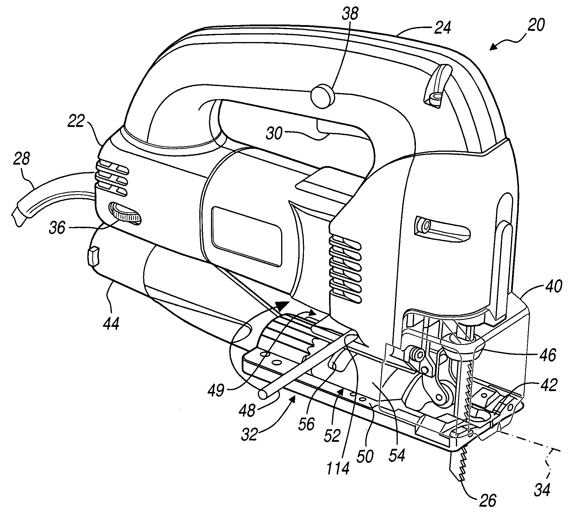
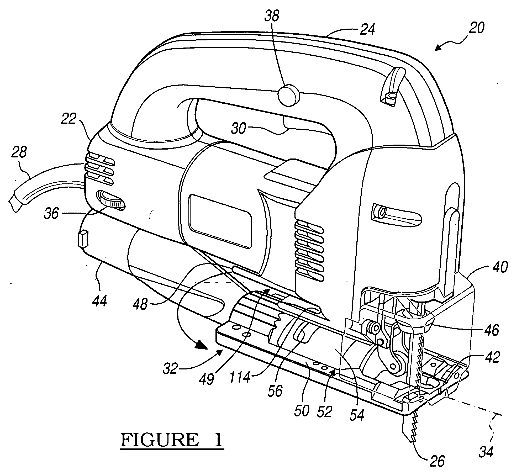
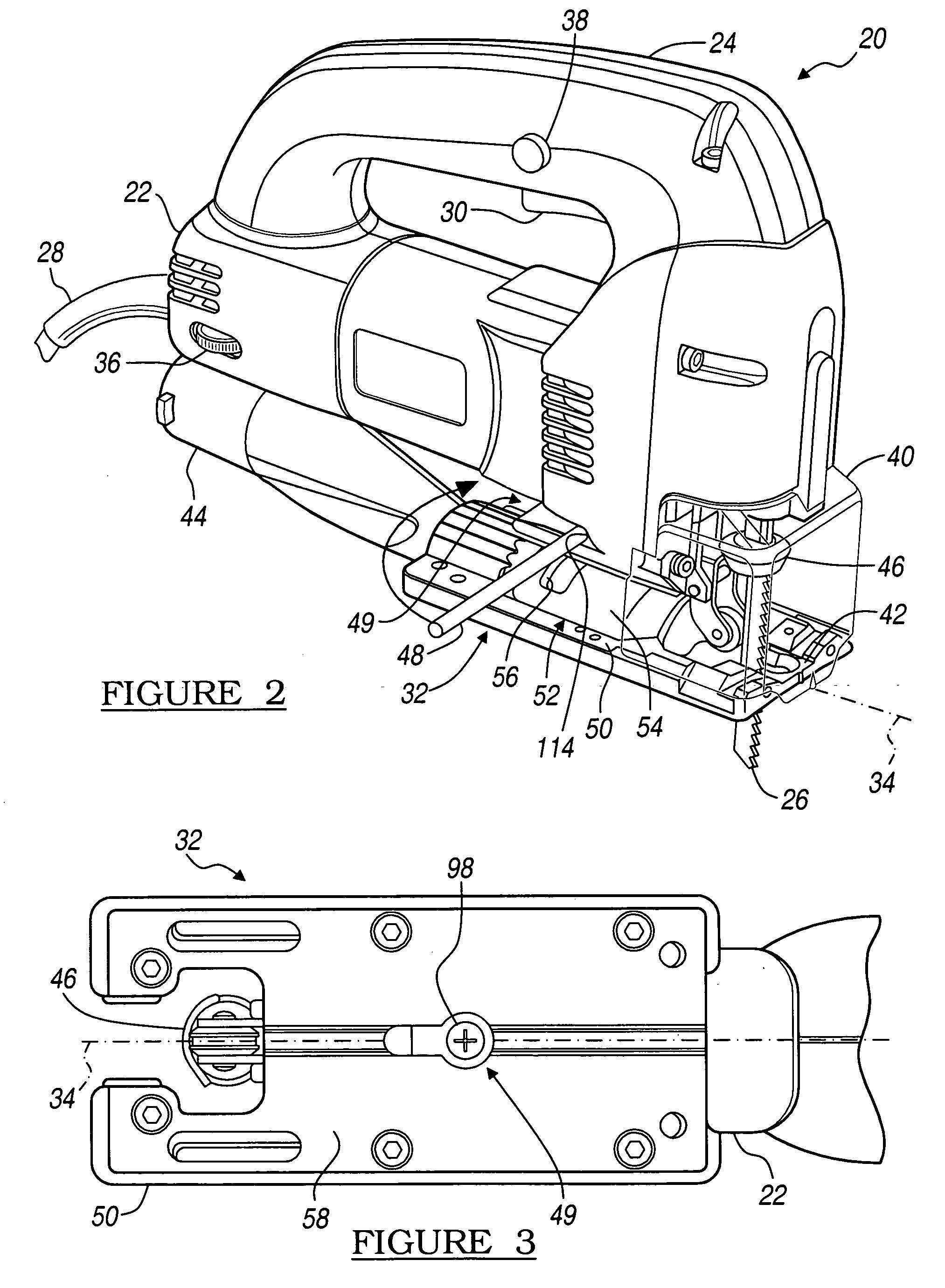
[0025] Referring to FIGS. 1 and 2, a preferred embodiment portable power tool is illustrated in accordance with the present invention, commonly referred to as a reciprocating saw, particularly a jigsaw 20. The jigsaw 20 includes a housing 22, and a handle 24 affixed to the housing. Specifically, a D-handle is illustrated, however the invention contemplates any handle, such as a barrel handle that may be formed as part of the housing that encloses a motor and operating mechanism of the saw. A motor (not shown) is disposed in the housing 22 for providing rotary motion to an operating mechanism (not shown) that converts the rotary motion to reciprocal motion for driving a saw blade 26 in a reciprocating or orbital-reciprocating motion, which is well known in the art. A power source 28 is provided to the jigsaw 20 which is controlled by trigger switch 30 for selectively imparting the reciprocating motion to the saw blade 26.

[0026] The jigsaw 20 is a portable saw and is commonly used b...


PUM

PropertyMeasurementUnit
bevel angleaaaaaaaaaa
diameteraaaaaaaaaa

Abstract

The present invention discloses an adjustable base for a portable saw and a portable saw therefore. The base includes a longitudinal shell secured to the housing, and mounted to a baseplate. A shaft is mounted to the housing extending through a slot formed in the shell. A collar is connected to the shaft and has a first cam surface cooperating with a corresponding second cam surface of the housing. Rotation of the collar in an unlocked direction extends the shaft away from the housing. A clamp member is received within a shell inner region and cooperates with the shaft. The shaft is threadably engaged to one of the collar, the housing or the clamp member so that rotation of the collar in the unlocked direction either extends the shaft further away from the housing or extends the clamp member along the shaft away from the housing.

Description

BACKGROUND OF THE INVENTION [0001] 1. Field of the Invention [0002] The invention relates generally to a portable power tool, particularly to an adjustable base therefore. [0003] 2. Background Art [0004] Conventional portable saws typically include a planar base upon which the tool is supported during the cutting operation to provide a consistent angle of cut relative to a top surface of an associated workpiece. Many conventional prior art portable saws are provided with an adjustable base for permitting a user to select an angle of the base relative to the cutting plane of the portable saw to thereby provide a user selected cutting angle relative to the surface of the workpiece. This angular adjustment of the cutting plane relative to the workpiece is commonly referred to as the bevel angle and is measured as the offset from orthogonal to the workpiece. [0005] Some conventional prior art portable saws with adjustable bases include a fastener, such as a threaded screw or bolt that m...

Claims


Application Information

Patent Timeline
Patent Type & Authority Applications(United States)
IPC IPC(8): B23D49/16
CPCB23D49/167
Inventor NGAN, ON SHANWONG, HEI PANG
Owner ONE WORLD TECH
Learn More