Eureka AIR delivers breakthrough ideas for toughest innovation challenges, trusted by R&D personnel around the world.

Compound differential dual power path transmission

a transmission mode and dual power path technology, applied in the field of vehicle transmissions, can solve the problems of reducing the efficiency of transmission, so as to achieve the effect of wide transmission ratio, relatively inexpensive and efficien

Inactive Publication Date: 2005-10-13
GM GLOBAL TECH OPERATIONS LLC
View PDF16 Cites 92 Cited by
  • Summary
  • Abstract
  • Description
  • Claims
  • Application Information

AI Technical Summary

Benefits of technology

[0013] The transmission of the invention may operate with fixed ratios, or may be employed with motor / generators as the first and second torque-transmitting devices to provide a large number of compound power split ratio ranges as a continuously variable transmission. The power required from the motor / generators in continuously variable operation is kept to a small fraction of power through the transmission while the ratio spread can be wide. The overall capacity or “corner power” of the motor / generators can also be kept as low as practical differential gearing will allow. Since hydraulic motors or electric motors are relatively expensive and inefficient as compared with gearing, limiting their size will help make the transmission relatively inexpensive and efficient.

Problems solved by technology

However, a series electric drive requires that the electrical machinery be sufficiently sized to transform all engine power from mechanical to electrical form and from electrical to mechanical form, and useful power is lost in this double conversion.
However, the prior art does not include any practical gear schemes with more than three compound split operating modes.

Method used


Image

  • Compound differential dual power path transmission
  • Compound differential dual power path transmission
  • Compound differential dual power path transmission

Examples


Embodiment Construction

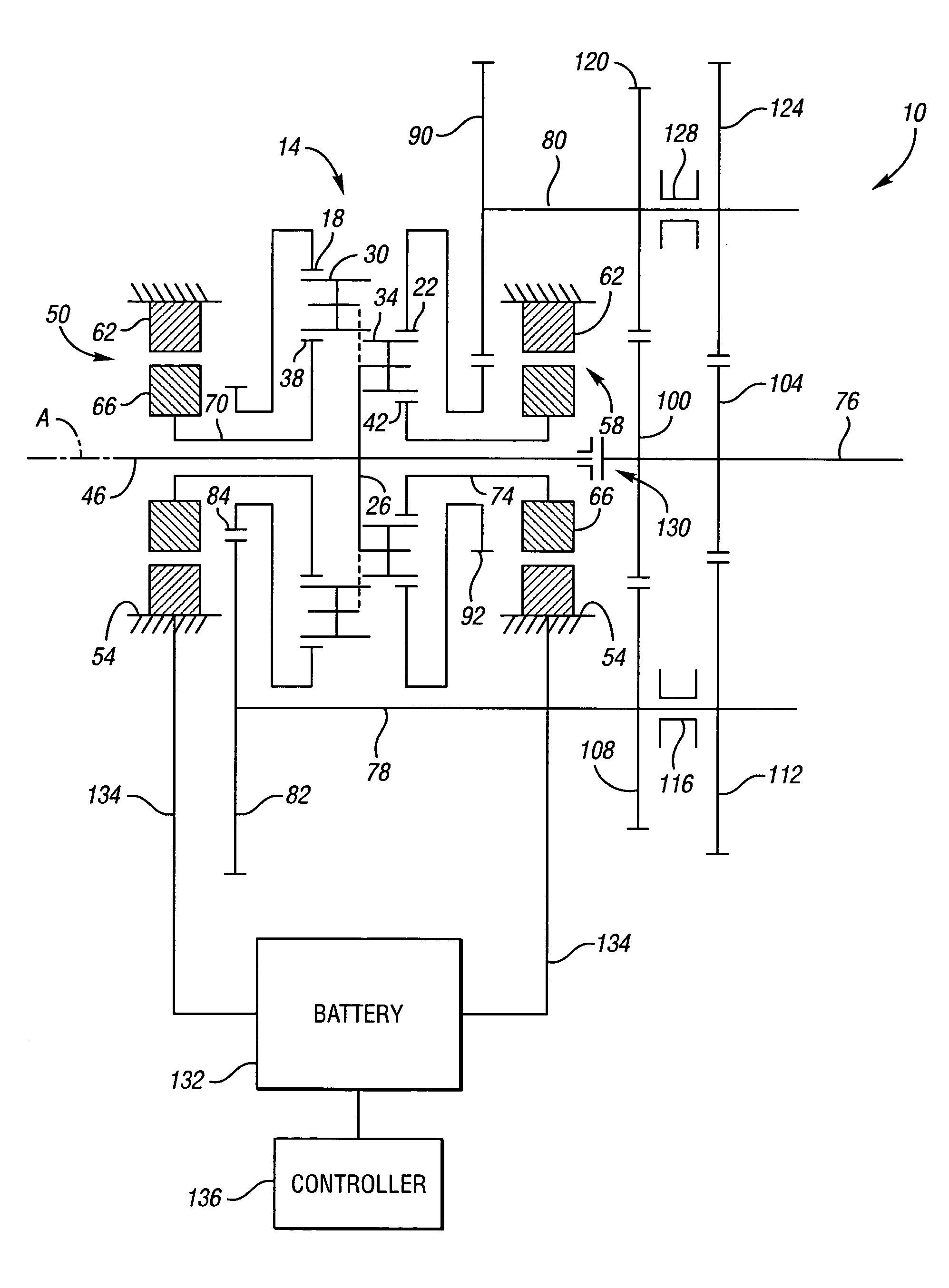
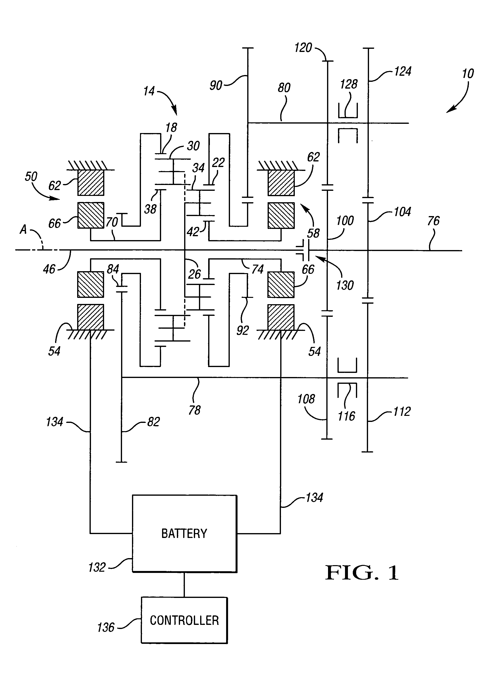
[0017] Referring to FIG. 1, a vehicular transmission 10 is schematically depicted. The transmission 10 includes a compound differential, Ravineaux gear set 14. The gear set 14 includes a first ring gear member 18, a second ring gear member 22, a planet carrier assembly member 26 including a first set of pinion gears 30 and a second set of pinion gears 34 rotatably mounted thereto, a first sun gear member 38, and a second sun gear member 42. The first sun gear member 38 is meshingly engaged with the first set of pinion gears 30. The second sun gear member 42 is meshingly engaged with the second set of pinion gears 34. The first ring gear member 18 is meshingly engaged with the first set of pinion gears 30, and the second ring gear member 22 is meshingly engaged with the second set of pinion gears 34. The first set of pinion gears 30 is meshingly engaged with the second set of pinion gears 34.

[0018] The differential gearset 14 has five members 18, 22, 26, 38, 42 on a common axis A, a...


PUM


Abstract

A vehicle transmission includes a differential gearset having five coaxial gear elements and two output members. Two of the gear elements are controllable via torque-transmitting devices such as friction brakes or electric motors to establish a plurality of speed ratios between the input shaft and the two output members. The two output members are selectively operatively connectable to an output shaft via a gear arrangement that allows for a plurality of speed ratios between the output members and the output shaft. If the torque-transmitting devices are electric motors or hydraulic pumps, then a continuously variable speed ratio between the input shaft and the output shaft is achievable. The plurality of speed ratios between the two output members and the output shaft enable a plurality of compound split operating modes, facilitating smaller and less powerful motors or pumps compared to the prior art.

Description

TECHNICAL FIELD [0001] This invention relates to vehicle transmissions having a differential gear set and two output members operatively interconnecting the gear set and an output shaft. BACKGROUND OF THE INVENTION [0002] A vehicle transmission can deliver mechanical power from an engine to the remainder of a drive system, typically fixed gearing, axles, and wheels. A transmission allows some freedom in engine operation, usually through alternate selection of five or six different drive ratios, a neutral selection that allows the engine to operate accessories with the vehicle stationary, and clutches or torque converters that allow smooth transitions between driving ratios to start the vehicle from rest and accelerate to the desired highway speed with the engine turning. Transmission gear selection typically allows power from the engine to be delivered to the rest of the drive system with a ratio of torque multiplication and speed reduction, with a ratio of torque reduction and spee...

Claims


Application Information

Patent Timeline
Patent Type & Authority Applications(United States)
IPC IPC(8): B60K1/02F16H3/00F16H3/72F16H37/08F16H48/06
CPCB60K1/02B60K6/365B60K6/445F16H3/006Y02T10/6239F16H2037/103F16H2200/0034F16H2200/2025F16H3/728Y02T10/62
Inventor HOLMES, ALAN G.
Owner GM GLOBAL TECH OPERATIONS LLC
Why Eureka
Eureka Blog
Learn More