
Tire-detecting wheel chock apparatus

a technology of wheel chocking and wheel chocking, which is applied in the field of vehicles, can solve the problems of undesirable gap between the trailer floor and the docking bay edge, unsuitable and potentially dangerous gap between the rearwardmost edge, and trailers that can have a tendency to “walk” or otherwise move away from the loading dock

Inactive Publication Date: 2005-10-13
HENDRICKSON USA L L C
View PDF18 Cites 40 Cited by
  • Summary
  • Abstract
  • Description
  • Claims
  • Application Information

AI Technical Summary

Benefits of technology

[0011] Objectives of the present invention include providing a wheel chock capable of ensuring and indicating correct positioning of the chock against a vehicle tire mounted on the wheel.
[0012] Another objective of the present invention includes providing such a wheel chock which is economical, durable and easy to use and maintain.

Problems solved by technology

However, the geometry of such air-ride axle / suspension systems can cause the trailer wheels and tires to rotate in a forward direction or away from the loading dock during a loading or unloading operation.
This well-known phenomenon thus can create an undesirable and potentially dangerous gap between the rearwardmost edge of a trailer floor and the edge of a loading dock.
More specifically, on vehicles having trailing or leading arm air-ride or leaf spring axle / suspension systems, and depending on the speed, direction, etc., at which a towmotor enters or exits the trailer, the force of the turning towmotor wheels themselves actually can also force a trailer away from a loading dock, thereby creating an undesirable gap between the trailer floor and docking bay edge.
Thus, as a towmotor repeatedly drives onto and off of a trailer bed to unload or load a trailer, the trailer can have a tendency to “walk” or otherwise move away from the loading dock.
Eventually, such walk or other movement can cause the towmotor tires to become stuck between or even fall into the gap created between the trailer bed and the loading dock, which can damage the cargo being loaded / unloaded and / or the towmotor, and possibly even cause injury to the towmotor operator.
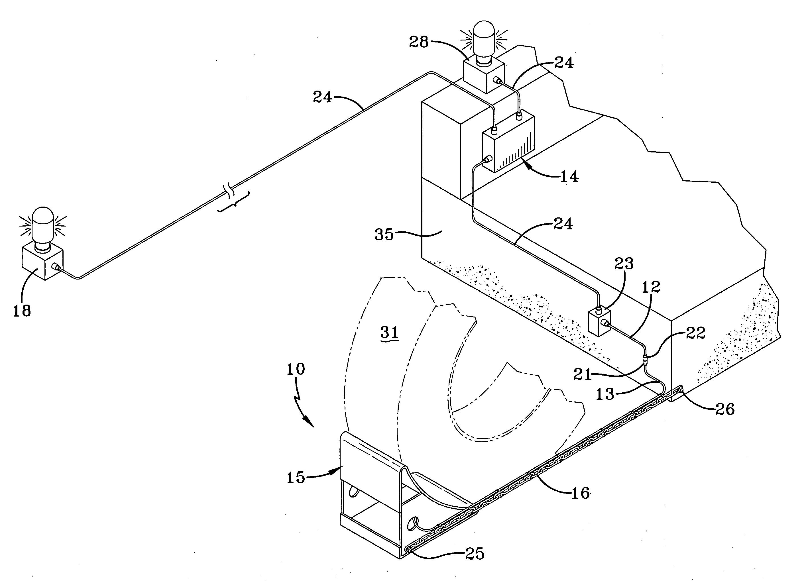
However, a towmotor operator typically cannot quickly visually verify that the wheel chocks are correctly wedged against the tires and the surface on which those tires rest, but instead must rely on and trust that the driver has satisfactorily accomplished this task.
Unfortunately, a driver occasionally either will forget to position the wheel chocks altogether or position them improperly, so that unbeknownst to the towmotor operator, trailer walk or other trailer movement is occurring, creating a potentially inconvenient or unsafe situation for property and person.

Method used


Image

  • Tire-detecting wheel chock apparatus
  • Tire-detecting wheel chock apparatus
  • Tire-detecting wheel chock apparatus

Examples


first embodiment

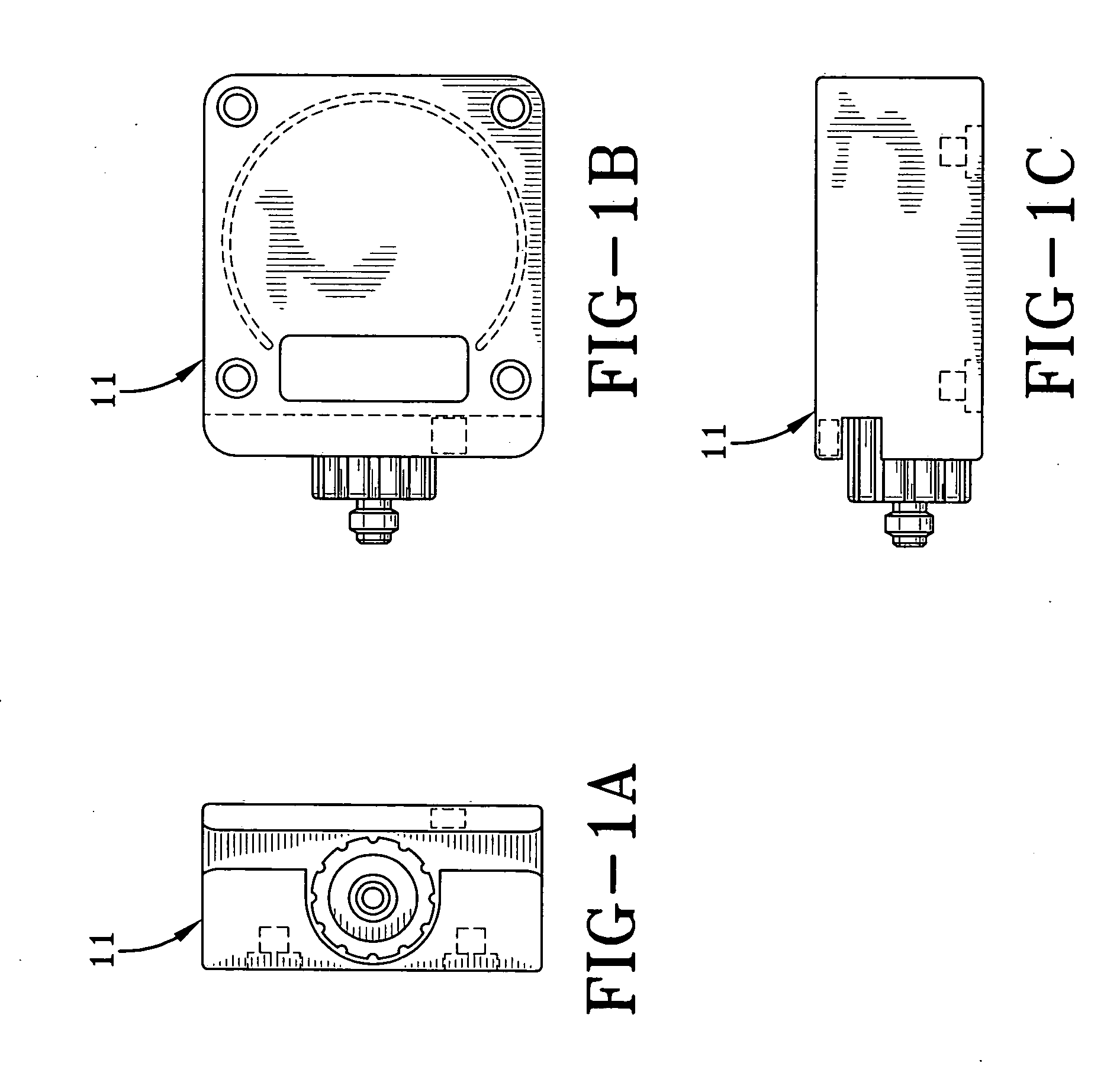
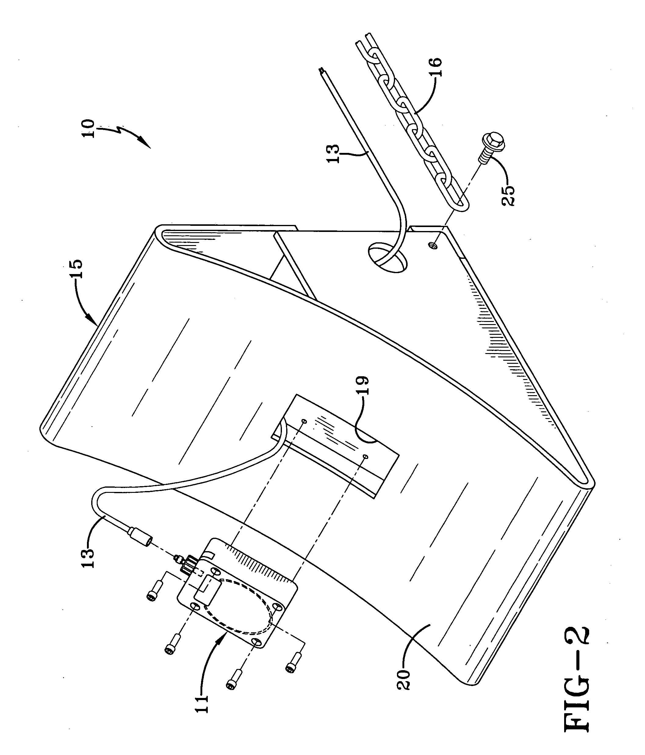
[0028] a tire-detecting wheel chock apparatus of the present invention useful in solving the above-described problems is indicated generally at 10 and is shown, except for the microcontroller and indicator means of the apparatus described below, in FIGS. 2 and 2A. More particularly, the improved chock apparatus of the present invention utilizes a sensor 11, as best shown in FIGS. 1A-1C, preferably capable of detecting a steel belt 30 of a tire 31 (FIG. 3) mounted on a wheel of a trailer (both not shown). Specifically, sensor 11 is an inductive proximity sensor of the type well-known in the art capable of and having a weld field immune range of about 50 millimeters. More specifically, a weld field immune sensor such as sensor 11 useful in the present invention, is one that emits a magnetic field to enable it to perform its sensing function, but is unaffected by, or immune to, unrelated electromagnetic forces it may encounter, such as a high voltage transformer located adjacent to a l...

second embodiment

[0033] It is understood that the concepts of tire-detecting wheel chock apparatus 10 of the present invention are applicable to nearly every type and varying size of chock body utilized in chocking heavy-duty vehicle tires, including rubber chock body 40 of second embodiment tire-detecting wheel chock apparatus 50 shown in FIGS. 5 and 6. Rubber chock body 40 and apparatus 50 operate generally identically to chock body 15 and apparatus 10, with the only difference being that sensor 11 preferably is embedded in chock body 40 during the rubber molding process.

[0034] It also is understood that the present invention contemplates different types of sensors having different types of detecting mechanisms, such as a motion detector with a certain range or a capacitive sensor capable of detecting a body such as the rubber of a tire, and / or detecting structure(s) or component(s) of the vehicle other than the tire, such as a portion of the trailer frame, or the like.

[0035] Moreover, it is unde...


PUM


Abstract

A wheel chock apparatus includes a chock body for chocking a tire of a vehicle such as a semi-trailer prior to loading or unloading the trailer by a towmotor at a docking bay. When properly positioned, the chock body prevents movement of the vehicle away from the docking bay during the loading or unloading operation. Such movement poses a possible hazard to the cargo being loaded or unloaded, to the equipment performing the loading / unloading operations, and to the operator of such equipment. The chock body includes a sensor mounted on or embedded in the body, which is capable of detecting a properly chocked tire. The sensor is electrically connected to a microcontroller programmed to control an indicator, such as a visual light or audible alarm, that will alert an equipment operator on the docking bay as to whether the driver of the vehicle has properly chocked the tires.

Description

BACKGROUND OF THE INVENTION [0001] 1. Field of the Invention [0002] The invention relates to vehicles that can be loaded and unloaded using a towmotor, and specifically to wheel chocks used to prevent movement of the vehicle during the loading and unloading operations. More particularly, the invention is directed to a wheel chock apparatus capable of detecting the presence of a tire and indicating to an individual performing a loading or unloading operation whether the trailer is properly chocked. [0003] 2. Background Art [0004] Heavy-duty vehicles such as semi-trailers or tractor-trailers typically include a trailer, which can be one of various types that are well-known in the heavy-duty vehicle art, and include van trailers and flatbed trailers. The trailers are used to haul cargo that typically is loaded onto and unloaded from the trailer at a loading dock or docking bay. Such heavy-duty vehicles also include box trucks, which do not have a separate trailer, but nonetheless have ...

Claims


Application Information

Patent Timeline
Patent Type & Authority Applications(United States)
IPC IPC(8): B60T3/00B65F9/00B65G69/00
CPCB60T3/00B65G2203/042B65G69/005
Inventor WILSON, JAMES D.
Owner HENDRICKSON USA L L C
Learn More