Optical member and method of producing the same
a technology of optical members and parts, applied in the field of optical parts, can solve the problems of difficult uniform formation of irregularities in low refractive index layers, unfavorable optical members, etc., and achieve excellent anti-reflection properties, reduce image contrast, and reduce the refractive index of parts
Inactive Publication Date: 2005-10-13
DAI NIPPON PRINTING CO LTD
View PDF3 Cites 2 Cited by
- Summary
- Abstract
- Description
- Claims
- Application Information
AI Technical Summary
Benefits of technology
[0006] The present invention has been accomplished in the light of these problems in the related art. An object of the present invention is therefore to provide an optical member having excellent anti-reflection properties, capable of being produced inexpensively as compared with conventional optical members having anti-reflection properties and of being mass-produced with quality kept constant, and a process of producing such an optical member.
[0023] According to the processes of producing optical members of the third and fourth means for fulfilling the object of the present invention, since the minute concavities and / or protrusions which a predetermined part of each optical member, selected from the planes of incidence and emergence of the optical member, has are shaped by a mold having, on its surface, minute protrusions and / or concavities that correspond to the minute concavities and / or protrusions which the predetermined part of the optical member has, the optical member can be mass-produced with quality kept constant. For this reason, the processes of the third and fourth means can attain stable supply of an optical member having excellent anti-reflection properties.
Problems solved by technology
It is difficult to uniformly form a low refractive index layer on the surface of an optical member by any of the above-described conventional processes, and the low refractive index layer formed often has irregularities.
Irregularities in a low refractive index layer are unfavorable to an optical member for use in a projection screen in particular.
Further, the conventional processes described above are disadvantageous also from the viewpoint of cost.
Furthermore, by any of the above-described conventional processes, it is difficult to conduct mass production of a low refractive index layer to obtain products that are identical in the strict sense of the word, so that it has been impossible to stably supply an optical member with quality kept constant.
Method used
View moreImage
Smart ImageViewing Examples
Examples
examples
[0050] A specific example of the above-described embodiments will be given below.
Login to View More PUM
| Property | Measurement | Unit |
|---|---|---|
| mean depth | aaaaa | aaaaa |
| mean depth | aaaaa | aaaaa |
| mean distance | aaaaa | aaaaa |
Abstract
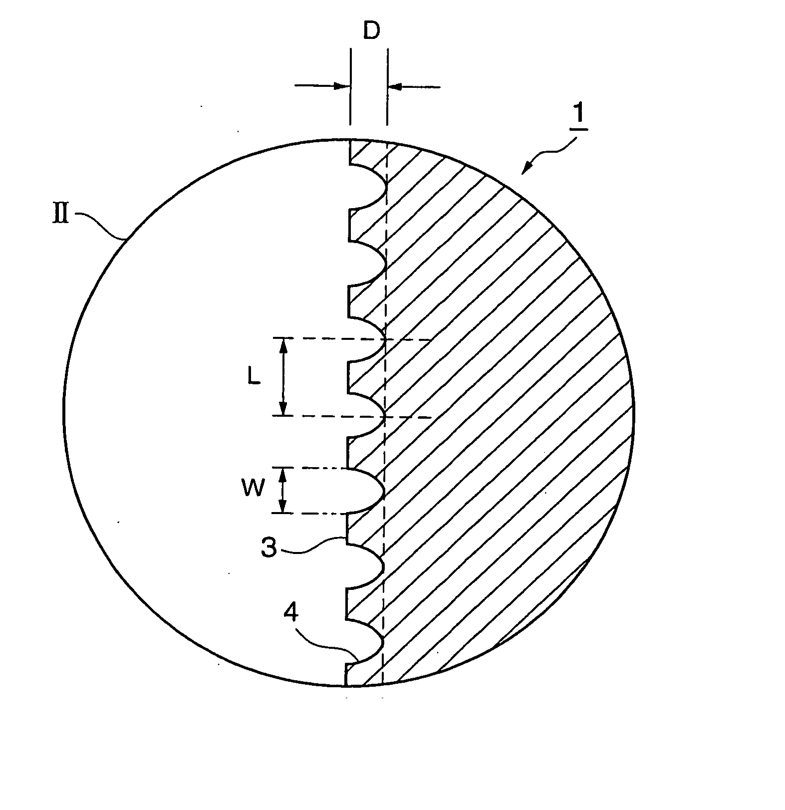
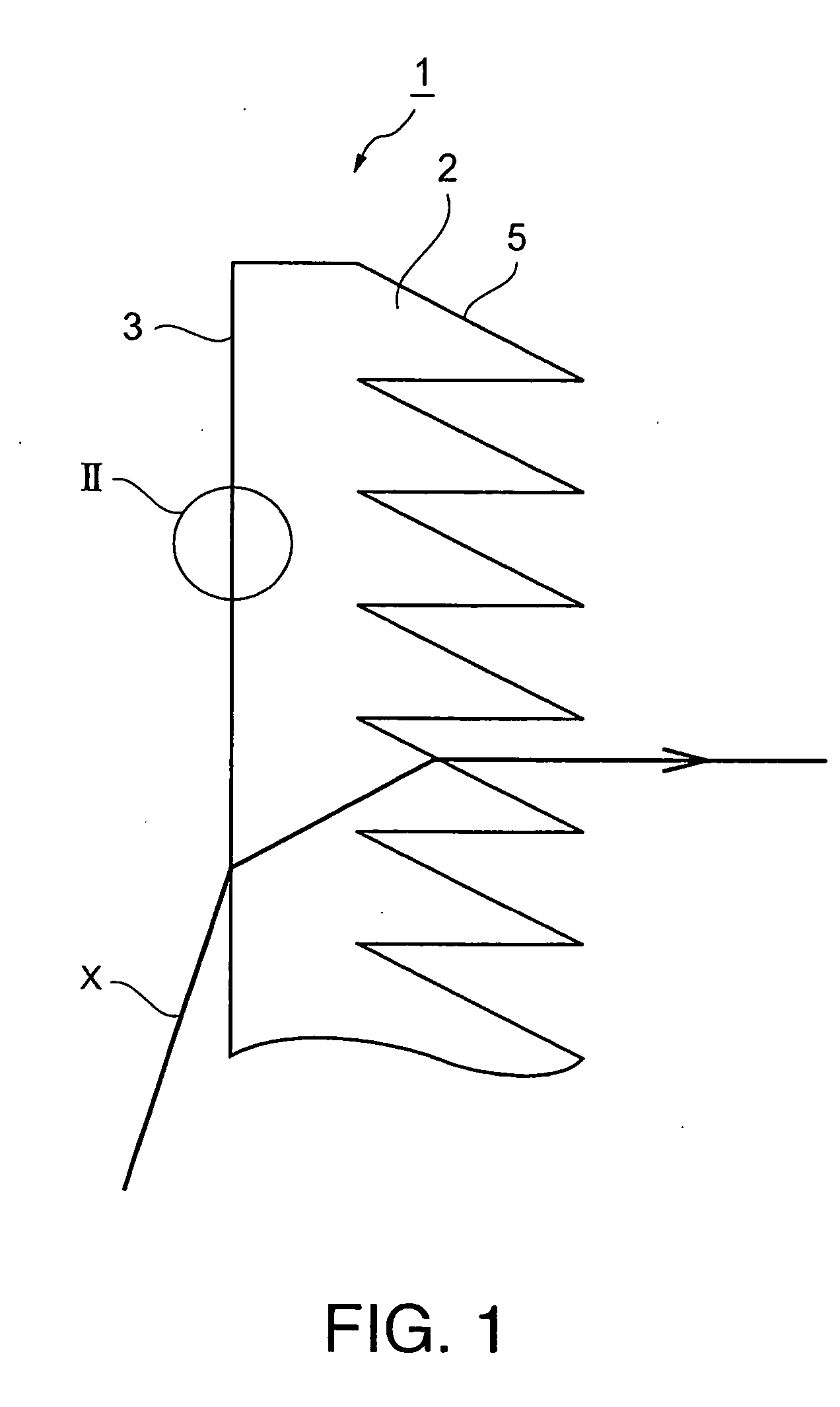
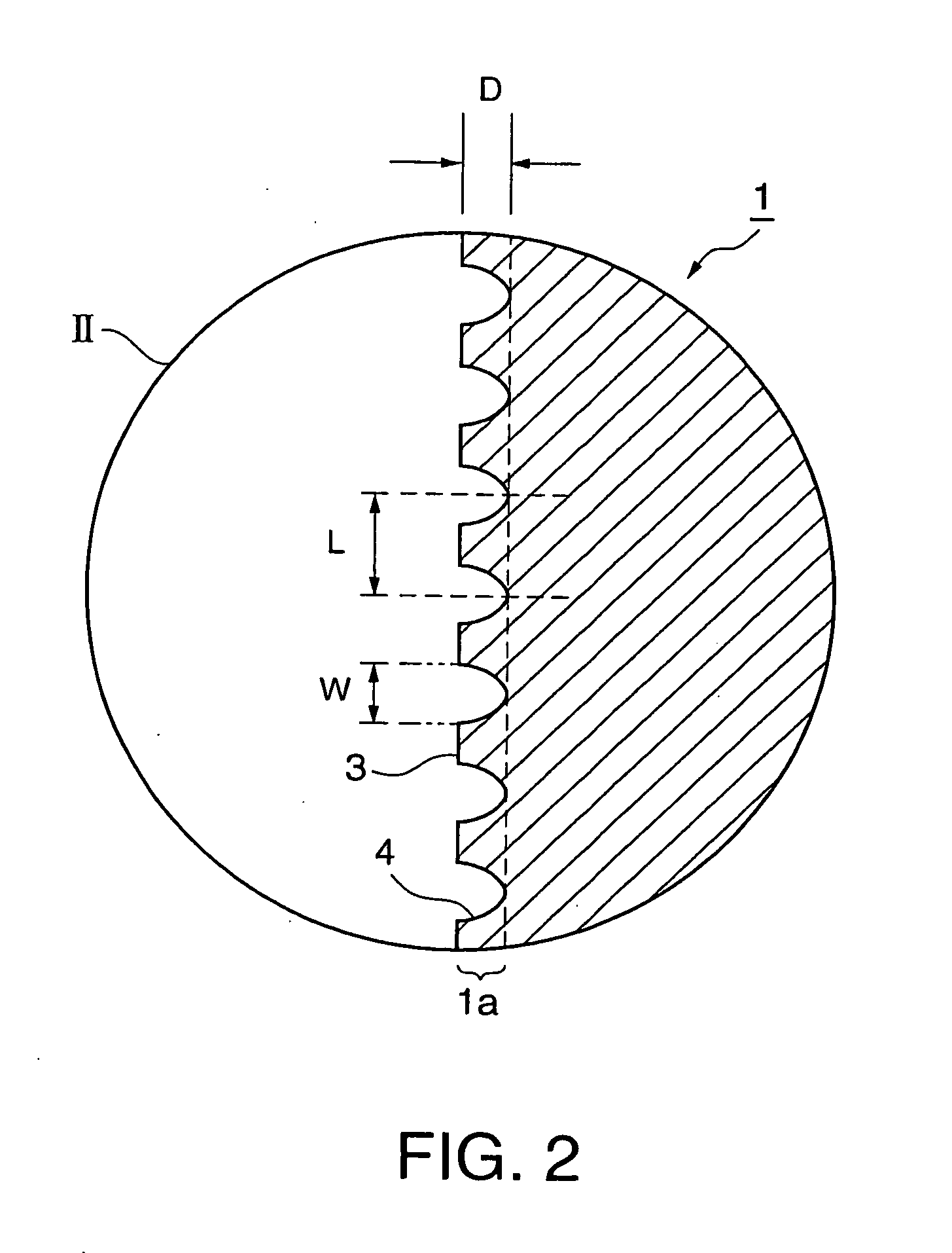
The present invention provides an optical member having excellent anti-reflection properties, capable of being produced inexpensively as compared with conventional optical members having anti-reflection properties and of being mass-produced with quality kept constant. An optical member 1 has a plane of incidence 3 and a plane of emergence 5. The plane of emergence 5 has, as an optical element, prisms 2 by which the optical path of incident light (see symbol X) is changed. The plane of incidence 3 has a plurality of minute concavities 4 (see FIG. 2) by which reflection of incident light is prevented.
Description
TECHNICAL FIELD [0001] The present invention relates to an optical member that can be advantageously used in a display such as a projection screen. More particularly, the present invention relates to an optical member whose planes of incidence and emergence can effectively prevent undesirable reflection of light, and to a process of producing the optical member. BACKGROUND ART [0002] For example, a projection screen uses a variety of optical members, such as a Fresnel lens sheet comprising an optical element for making light projected from an imaging light source follow optical paths that are approximately parallel to one another, and a lenticular lens sheet comprising an optical element for dispersing the light that have been made parallel by the Fresnel lens sheet. [0003] In such optical members, it is necessary to prevent, as much as possible, light (imaging light) projected from an imaging light source and light (external light) emitted from an external illuminant (e.g., a light...
Claims
Login to View More Application Information
Patent Timeline
 Patent Type & Authority Applications(United States)
IPC IPC(8): G02B1/11G02B1/118G02B3/08G03B21/62G03B21/625
CPCG02B1/11G02B5/04G02B5/02
Inventor GOTO, MASAHIRO
Owner DAI NIPPON PRINTING CO LTD
Features
- R&D
- Intellectual Property
- Life Sciences
- Materials
- Tech Scout
- Unparalleled Data Quality
- Higher Quality Content
- 60% Fewer Hallucinations
Learn More Browse by: Latest US Patents, China's latest patents, Technical Efficacy Thesaurus, Application Domain, Technology Topic, Popular Technical Reports.
© 2025 PatSnap. All rights reserved.Legal|Privacy policy|Modern Slavery Act Transparency Statement|Sitemap|About US| Contact US: help@patsnap.com


