Inverter-integrated motor for an automotive vehicle
- Summary
- Abstract
- Description
- Claims
- Application Information
AI Technical Summary
Benefits of technology
Problems solved by technology
Method used
Image
Examples
first embodiment
[0119] An inverter-integrated motor-driven compressor of a refrigerating cycle for an automotive vehicle in accordance with a first embodiment of the present invention will be explained with reference to accompanied drawings, although some of constituent members and lines are omitted.
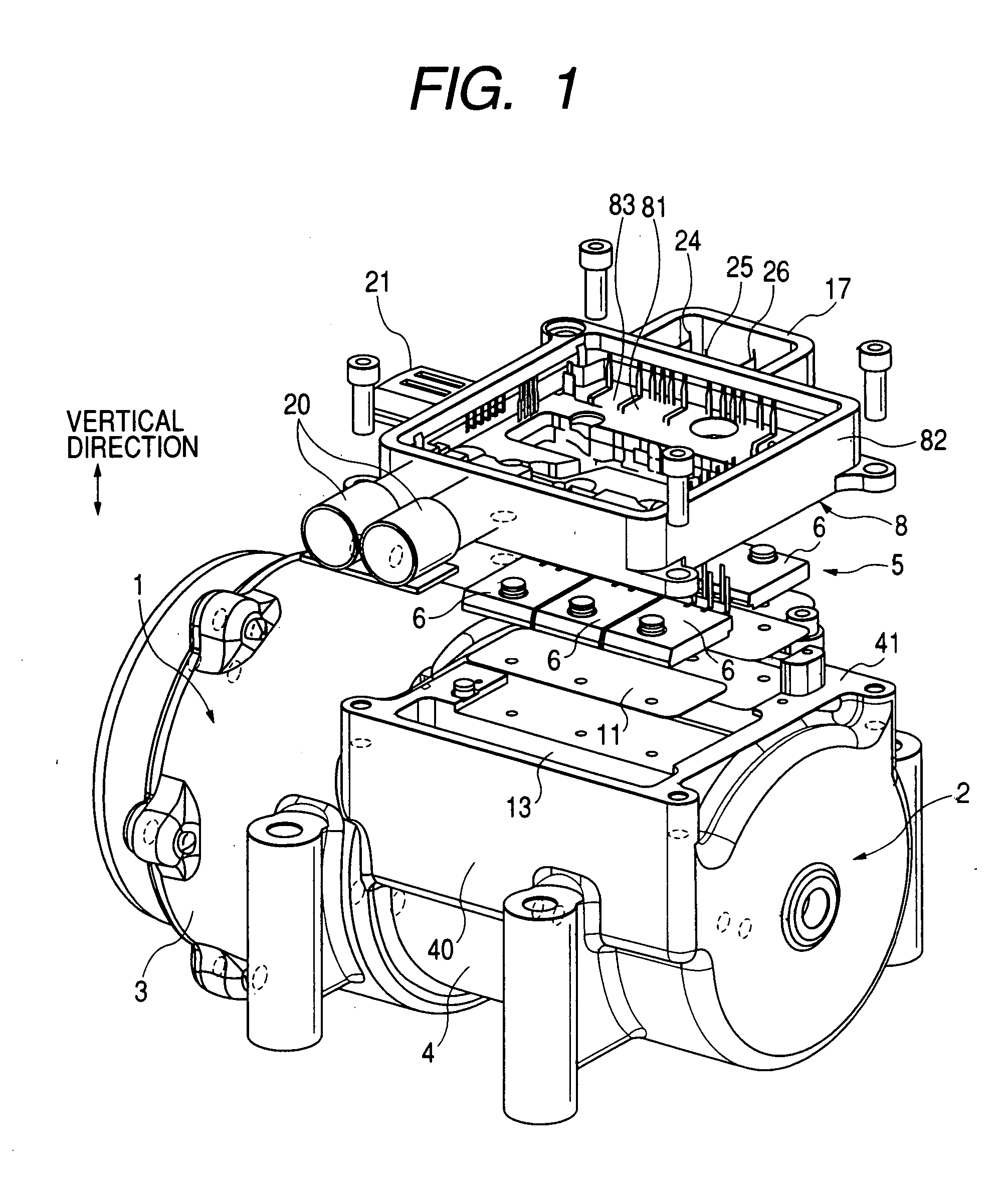
[0120]FIG. 1 is an exploded perspective view showing the inverter-integrated motor-driven compressor in accordance with the first embodiment of the present invention.
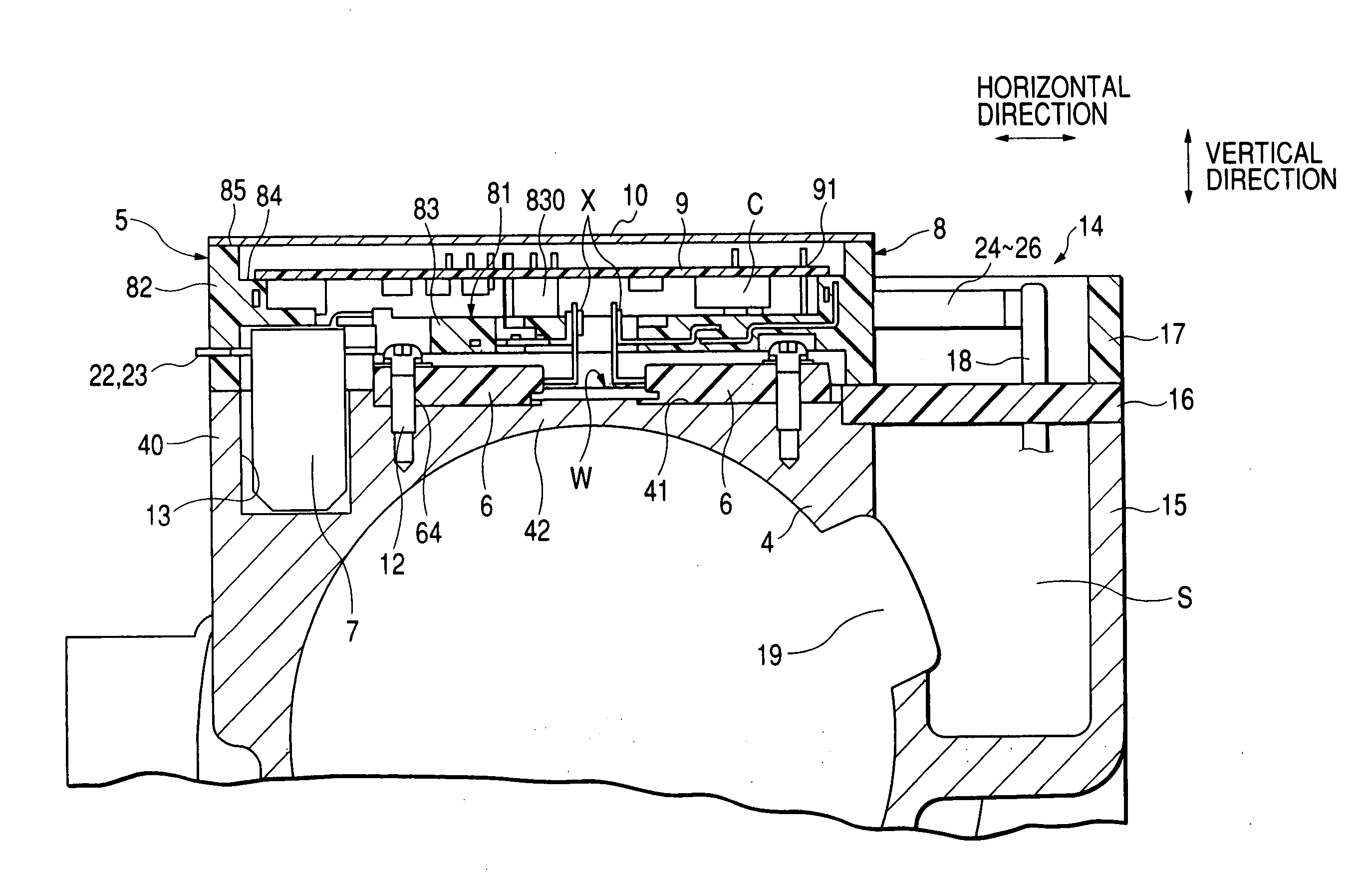
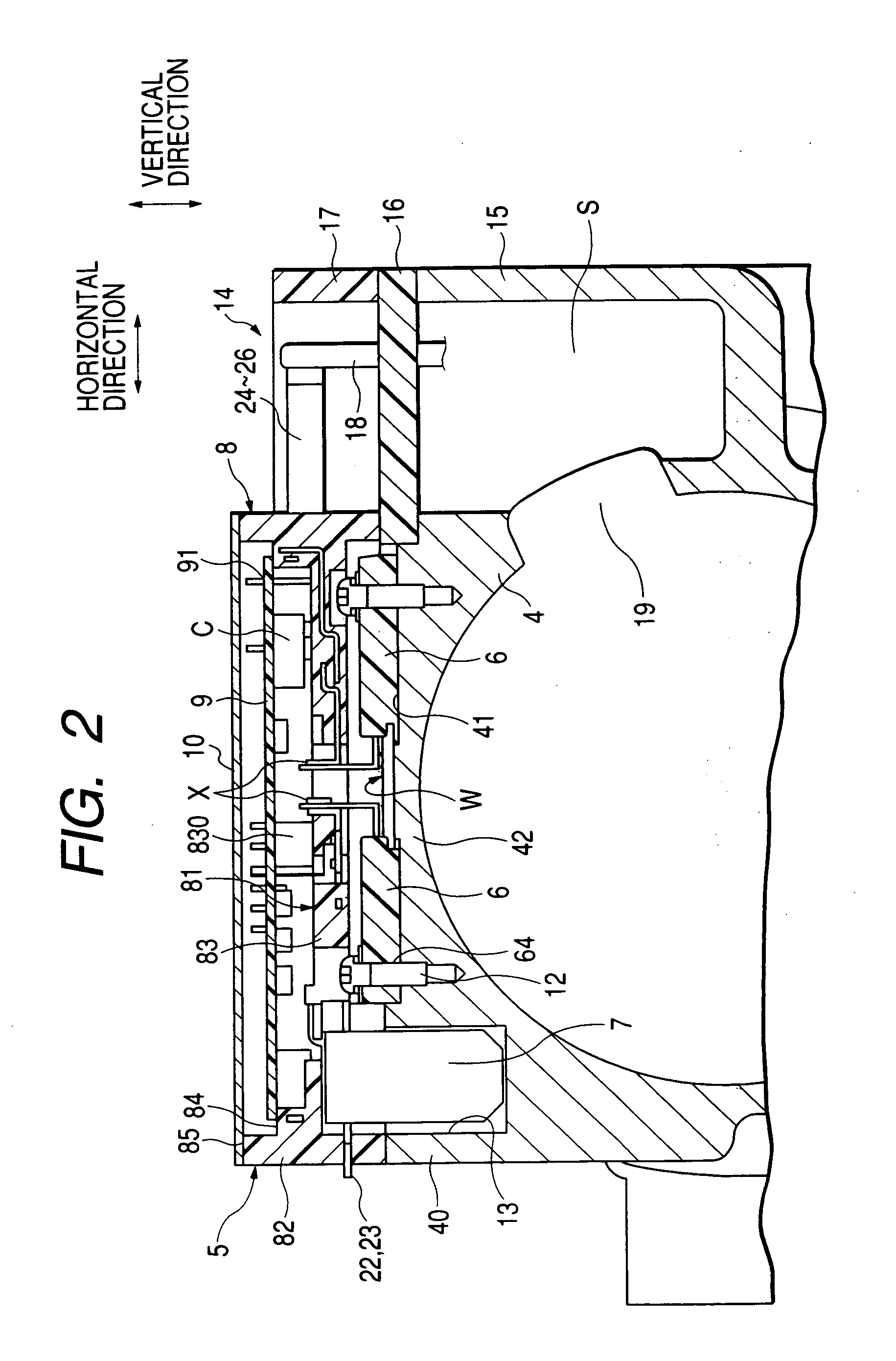
[0121]FIG. 2 is a cross-sectional view showing an inverter circuit section of the inverter-integrated motor-driven compressor shown in FIG. 1, taken along the radial direction of the compressor. FIG. 2 shows the inverter circuit attached to a housing of the motor driven compressor. FIG. 2 does not show a refrigerating circuit as it is conventionally well known.
[0122]FIG. 3 is an exploded perspective view showing a plurality of power MOS transistor modules 6 mounted on a mounting base surface 41 of a motor housing 4.
[0123]FIG. 4 is a pla...
second embodiment
Various Modifications of Second Embodiment
[0202]FIG. 11 a perspective view showing another inverter-integrated motor-driven compressor in accordance with the second embodiment. FIG. 12 is a rear view of the inverter-integrated motor-driven compressor shown in FIG. 11.
[0203] According to the inverter-integrated motor-driven compressor shown in FIGS. 11 and 12, an aluminum rib 2400 is provided so as to extend laterally or horizontally on one side surface of the mounting base portion 204 facing in the forward direction of the vehicle. This arrangement brings the effect of safely protecting the inverter circuit section 203 in case of car crash.
[0204]FIG. 13 a perspective view showing another inverter-integrated motor-driven compressor in accordance with the second embodiment. FIG. 14 is a rear view of the inverter-integrated motor-driven compressor shown in FIG. 13.
[0205] According to the inverter-integrated motor-driven compressor shown in FIGS. 13 and 14, four protruding portions 2...
third embodiment
[0208] An inverter-integrated motor-driven compressor of a refrigerating cycle for an automotive vehicle in accordance with a third embodiment of the present invention will be explained with reference to accompanied drawings, although some of constituent members and lines are omitted. FIG. 15 is an exploded perspective view showing the inverter-integrated motor-driven compressor in accordance with the third embodiment of the present invention. FIG. 16 is a perspective view showing a bus-bar assembly to be incorporated in the inverter-integrated motor-driven compressor in accordance with the third embodiment of the present invention. FIG. 17 is a perspective view showing bus bars to be molded in the bus-bar assembly shown in FIG. 16. FIG. 18 is an exploded perspective view showing the bus-bar assembly and power switching elements to be assembled together. FIG. 19 is a plan view showing the inverter-integrated motor-driven compressor shown in FIG. 15, although a cover plate and a prin...
PUM
 Abstract
Description
Claims
Application Information
 - R&D
- Intellectual Property
- Life Sciences
- Materials
- Tech Scout
- Unparalleled Data Quality
- Higher Quality Content
- 60% Fewer Hallucinations
Browse by: Latest US Patents, China's latest patents, Technical Efficacy Thesaurus, Application Domain, Technology Topic, Popular Technical Reports.
© 2025 PatSnap. All rights reserved.Legal|Privacy policy|Modern Slavery Act Transparency Statement|Sitemap|About US| Contact US: help@patsnap.com


