
In-vehicle mount type AV system and program

a technology of av system and vehicle, applied in the direction of dynamo-electric converter control, roof, instruments, etc., can solve the problems of inaccurate detection of the position of the occupants, complex and expensive equipment, etc., and achieve the effect of suitable acoustic effect control and simple construction

Inactive Publication Date: 2005-10-06
DENSO CORP
View PDF17 Cites 13 Cited by
  • Summary
  • Abstract
  • Description
  • Claims
  • Application Information

AI Technical Summary

Benefits of technology

[0006] The present invention has been implemented in view of the foregoing situation, and has an object to provide a technique that can implement suitable acoustic effect control with a simple construction.
[0009] As described above, the construction itself is simple although the proper acoustic effect control can be implemented. That is, it is originally effective to occupants viewing display contents that the display face angle of the display unit is varied, and it is preferable to implement this construction irrespective of control or non-control of the acoustic effects. Accordingly, if the angle varying unit (for example, motor) described above is provided, the varied angle can be detected by only detecting the rotational angle of the motor, for example, and thus the construction can be made very simple. That is, in the publication described above, an image pickup camera, an image analysis processor, etc. are needed, and a complicated and expensive apparatus is needed. However, in the case of the in-vehicle mount type AV system of the present invention, the proper control of the acoustic effects can be implemented while maintaining a simple and inexpensive configuration. However, the positions of the occupants are estimated from first to last, and the positions of the occupants are not accurately detected unlike the case where the image pickup camera and the image analysis processor are used. However, a sufficient effect can be achieved by using even the occupant detecting method based on the estimation according to the present invention, leading to enhanced effectiveness.
[0010] The display unit may be used for front seats or rear seats, and at least a display unit for the rear seats may be targeted. The display unit for the front seats may be targeted. The display unit for the front seats is frequently set so that only the navigation screen is displayed during travel of the vehicle out of consideration to safety. Accordingly, when a user watches AV for a general entertainment, the display for the rear seats is actually more effective. In this sense, the present invention is very effective to a rear entertainment system (a system in which occupants at the rear seats enjoy AV).
[0011] It is preferable that the angle varying unit can vary the display face angle of the display unit at least in the right and left direction. When an occupant sits at only one of the right and left seats, the optimum acoustic effect control targeting the occupant concerned can be implemented. Of course, the effect can be achieved even when the display face angle is varied only in the vertical direction. That is, in the case of an adult and a child which are different in seating height, the head positions thereof are different from each other. Accordingly, the acoustic effect may be controlled in accordance with the head positions. However, since the varied angle of the display face is actually larger in the right and left direction than in the vertical direction, and thus it is a more realistic manner to make the display face variable at least in the right and left direction.

Problems solved by technology

That is, in the publication described above, an image pickup camera, an image analysis processor, etc. are needed, and a complicated and expensive apparatus is needed.
However, the positions of the occupants are estimated from first to last, and the positions of the occupants are not accurately detected unlike the case where the image pickup camera and the image analysis processor are used.

Method used


Image

  • In-vehicle mount type AV system and program
  • In-vehicle mount type AV system and program
  • In-vehicle mount type AV system and program

Examples


Embodiment Construction

[0021] Embodiments according to the present invention will be described with reference to the accompanying drawings. The present invention is not limited to the following embodiments, and various modifications may be made without departing from the subject matter of the present invention.

[In-Vehicle Mount Type AV System]

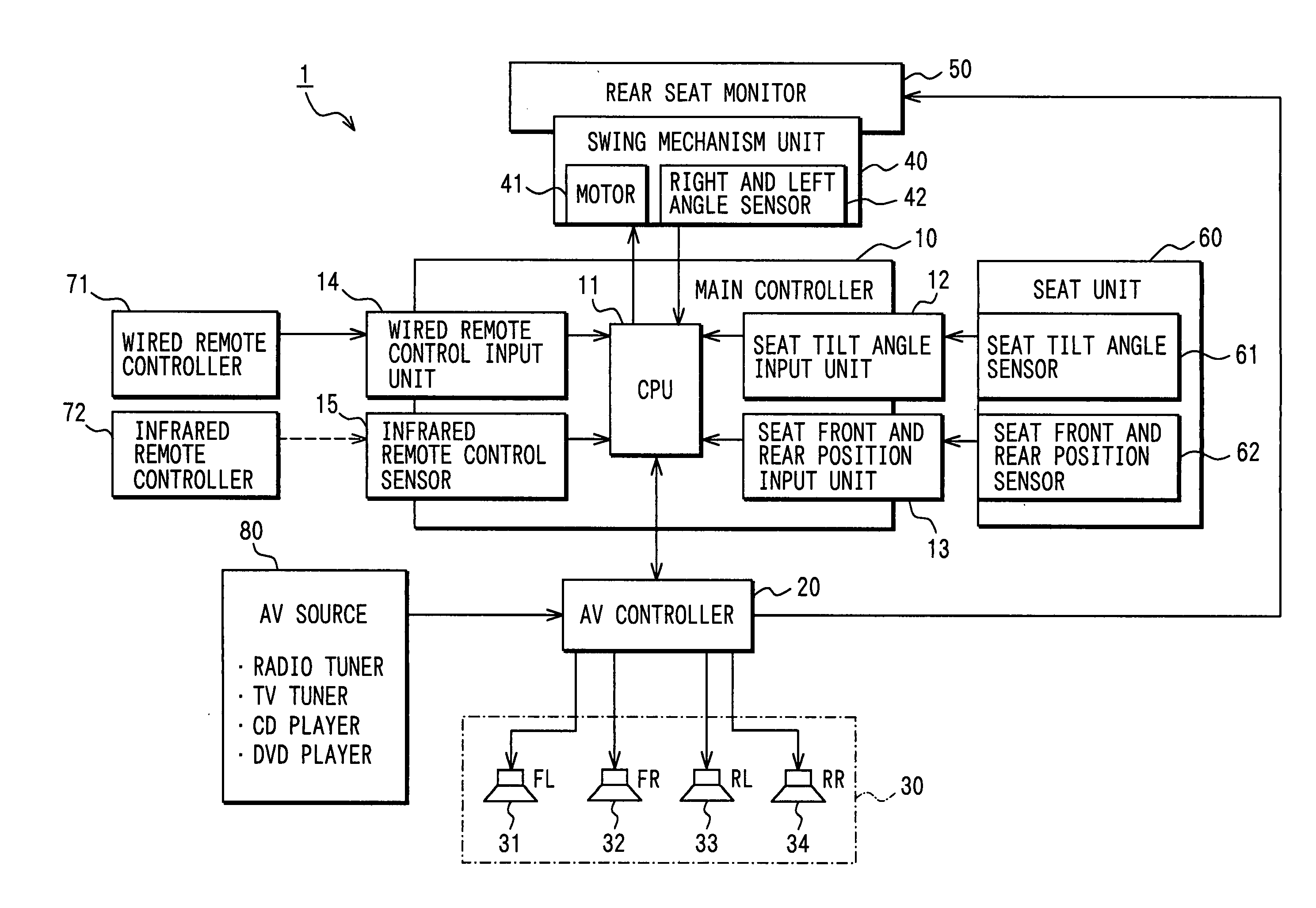
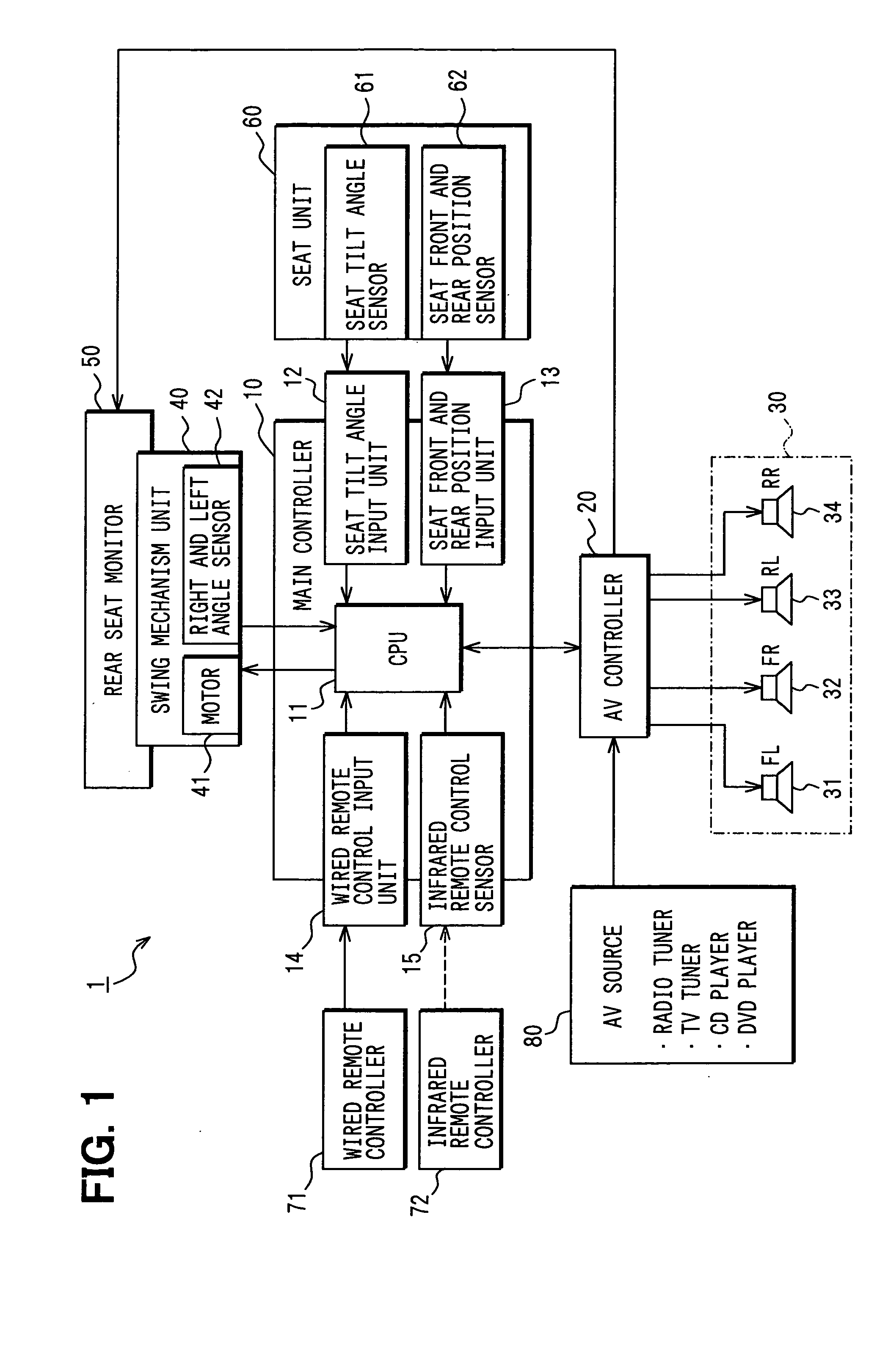
[0022]FIG. 1 is a block diagram showing the construction of an in-vehicle mount type AV system 1 according to an embodiment.

[0023] The in-vehicle mount type AV system 1 of this embodiment is mounted in a vehicle, and it comprises a main controller 10, an AV controller 20, a speaker group 30, a swing mechanism unit 40, a rear motor 50, a seat tilt angle sensor 61 and a seat front and rear position sensor 62 which are provided to the seat unit 60, a wired remote controller 71, an infrared remote controller 72 and an AV source 80.

[0024] The main controller 10 has a CPU 11, a seat tilt angle input unit 12, a seat front and rear position input unit 13, a wired remote ...


PUM


Abstract

In an in-vehicle mount type AV system for implementing proper acoustic effect control, a swing angle of a rear monitor is detected by a right and left angle sensor, and respective acoustic effects of four speakers (for example, the volume levels of reproduced sounds) are adjusted. The angle detected by the right and left angle sensor corresponds to the angle of the display face of the rear monitor, and the correlation between the display face and the head position of an occupant (automobile passenger) can be estimated. That is, the probability that the head portion of the occupant exists in a direction to which the display face of the rear monitor is oriented is high, and thus the acoustic effect is controlled so that proper volume balance is established at the occupant position thus estimated.

Description

CROSS REFERENCE TO RELATED APPLICATION [0001] This application is based on and incorporates herein by reference Japanese Patent Application No. 2004-112256 filed on Apr. 6, 2004. FIELD OF THE INVENTION [0002] The present invention relates to an AV (Audio Visual) system mounted in a vehicle. BACKGROUND OF THE INVENTION [0003] With respect to volume control of car audio, there is known a technique of controlling volume balance in accordance with the number of occupants in a vehicle and the positions of the occupants (for example, see JP-A-9-83277). [0004] In the technique disclosed in the above publication, the number of occupants and the positions of the occupants are detected on the basis of image recognition and detection of body temperature, and the volume of sounds emitted from plural speakers (for example, every two speakers at each of front and rear seats, totally four speakers) is controlled in accordance with the detection results. [0005] When the method disclosed in the abov...

Claims


Application Information

Patent Timeline
Patent Type & Authority Applications(United States)
IPC IPC(8): B60R11/02H03K19/177G06F7/00H04R3/00
CPCB60R11/0217H03K19/177
Inventor FUKURO, HIDEKI
Owner DENSO CORP
Learn More