
Cardiac pacemaker

Active Publication Date: 2005-10-06
BIOTRONIK SE & CO KG
View PDF17 Cites 18 Cited by
  • Summary
  • Abstract
  • Description
  • Claims
  • Application Information

AI Technical Summary

Benefits of technology

[0036] It is to be noted that embodiments of the present invention presented herein do not require measurement of the evoked potential and therefore avoids on the one hand the technical complication and expenditure linked to such measurement and on the other hand avoids certain disadvantages involved in a method which is based on checking only for a short time after the pulse whether there is an evoked potential (U.S. Pat. No. 5,601,615), in which however the interaction between stimulation and the intrinsic rhythm (natural cardiac rhythm) is disregarded. Those disadvantages include uncertainties which, in the previous approaches, under certain conditions, can result in limited sensitivity and / or specificity of the algorithm for automatic detection of the atrial stimulus response (for example in the case of an atrial fusion systole or in the event of excessively high polarization voltage after pulse delivery).
[0046] An electrostimulator whose stimulation control unit is adapted to determine a capture control signal in dependence on whether the presence or absence of a natural cardiac rhythm is ascertained within the predetermined period of time and additionally or alternatively to produce a Loss-of-Capture signal (LOC) in the case of the presence of a natural cardiac rhythm within the predetermined period of time already affords the advantage of effective stimulation success checking.

Problems solved by technology

A further problem is that the far-field of a ventricular stimulus is also to be perceived (detected) in the atrium of a heart.
The stimulus threshold can change in the course of time and therefore a one-off stimulus threshold test upon implantation is generally not sufficient.
In actual fact however at the present time, for the atrium region, there is no implantable or external system with which fully automatic atrial threshold tracking or fully automatic atrial stimulus threshold determination can be reliably effected.
Those known approaches are unsatisfactory for various reasons.

Method used


Image

  • Cardiac pacemaker
  • Cardiac pacemaker
  • Cardiac pacemaker

Examples


Embodiment Construction

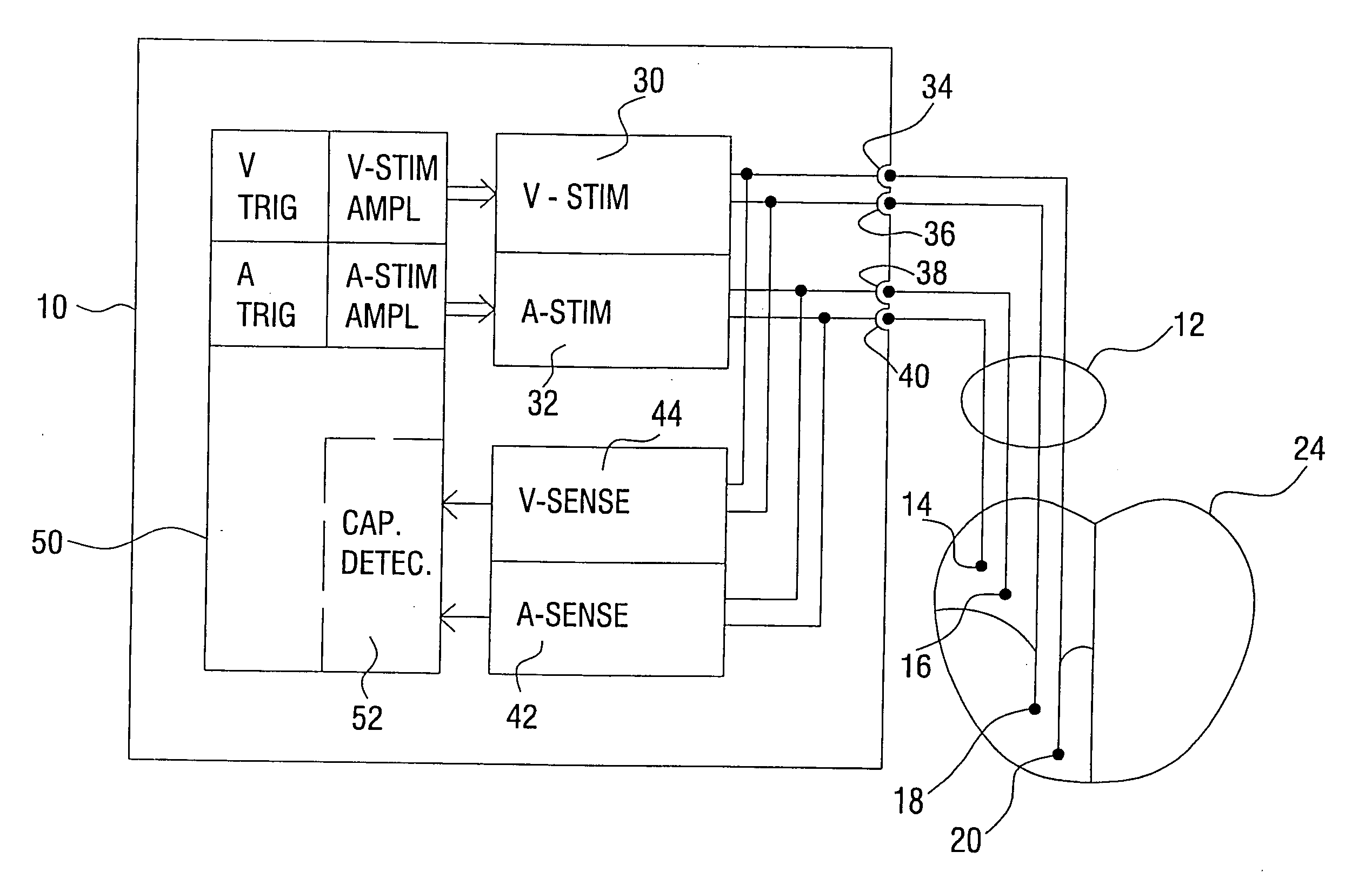
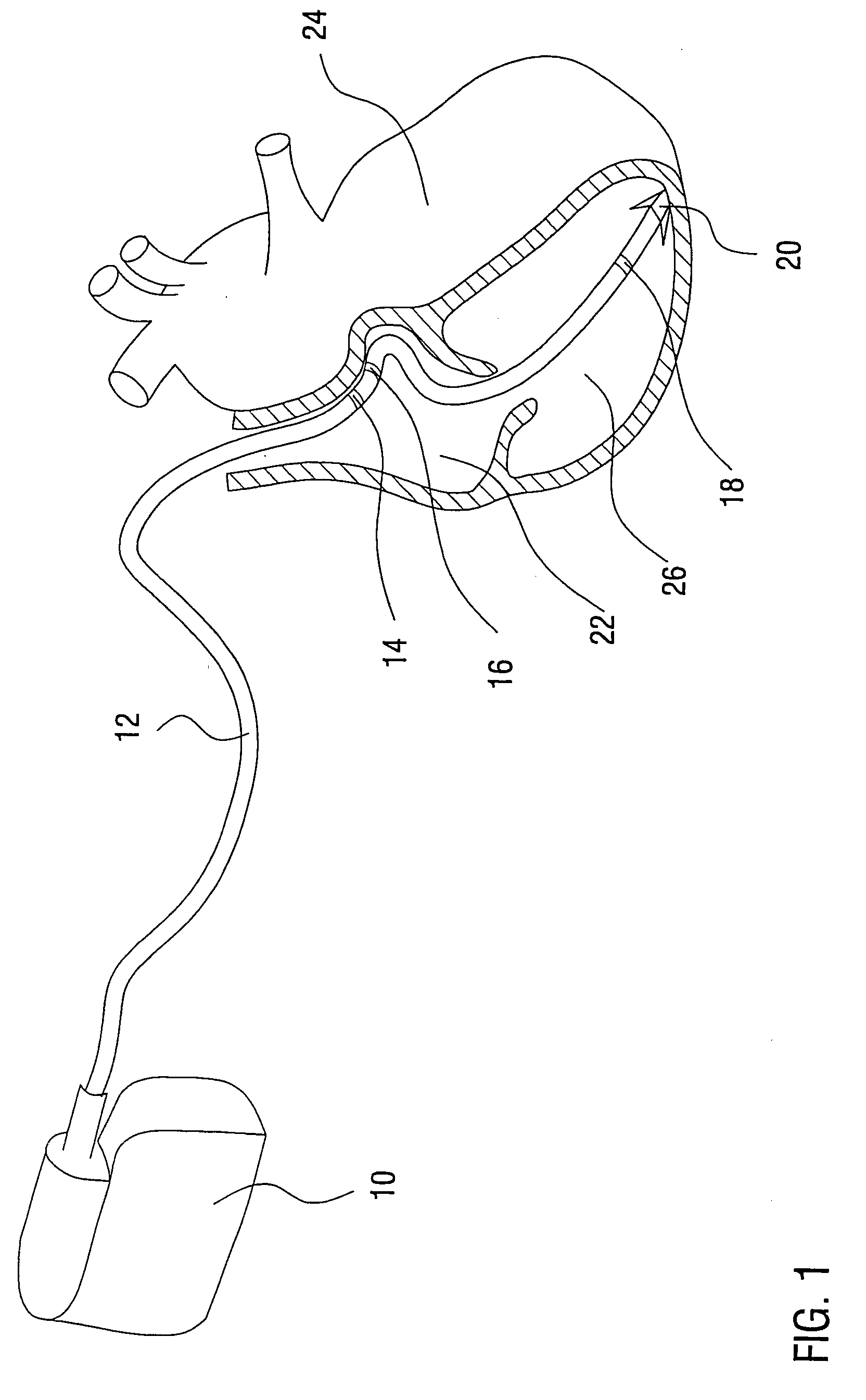
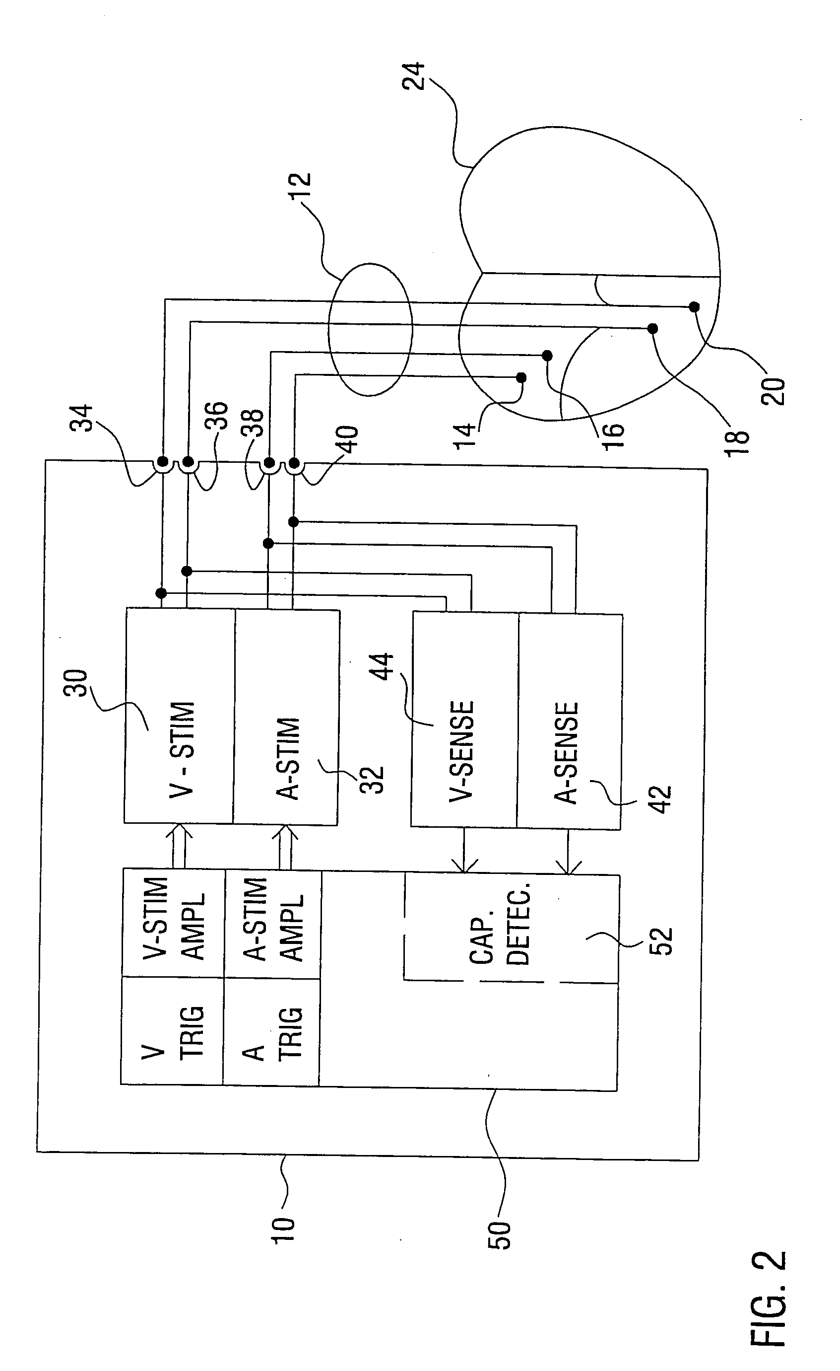
[0076]FIG. 1 shows as an implantable stimulation device, a cardiac pacemaker 10, to which is connected an electrode line 12 which has two atrial electrodes 14 and 16 and two ventricular electrodes 18 and 20 in the region of the distal end thereof. In FIG. 1 the atrial electrodes 14 and 16 are arranged in the atrium 22 of a heart 24 while the ventricular electrodes 18 and 20 are arranged in the ventricle 26 of the heart 24. Instead of a common electrode line 12 for atrium and ventricle, it is also possible to provide a respective electrode line with for example two electrodes, for each of the atrium and the ventricle. In the illustrated example the implantable stimulation device is a cardiac pacemaker. The device could equally well be a cardioverter or defibrillator. Equally the cardiac pacemaker 10 could also be in the form of a biventricular cardiac pacemaker with an electrode line for stimulation of the left electrode of a heart.

[0077] Certain components in the interior of the ca...


PUM


Abstract

Certain embodiments of the present invention disclose an electrostimulator, in particular an atrial cardiac pacemaker, comprising electrode connections which are connected to a stimulation unit for the delivery of stimulation pulses by way of the electrode connections, and a stimulation control unit which is connected to the stimulation unit and adapted to trigger the delivery of stimulation pulses and to determine the strength of the stimulation pulses and for that purpose to deliver a stimulation control signal to the stimulation unit, and a detection unit which is connected to the stimulation control unit and at least indirectly to the electrode connections and adapted to evaluate electrical potentials at the electrode connections and to detect intrinsic (natural, spontaneous) events. The stimulation control unit is adapted to produce a far-field signal if the detection unit detects an intrinsic atrial event within a predetermined far-field coupling interval which begins after triggering of a ventricular stimulation pulse.

Description

CROSS-REFERENCE TO RELATED APPLICATIONS / INCORPORATION BY REFERENCE [0001] This application claims priority to German patent application serial number 10 2004 017 137.8 filed on Apr. 1, 2004. TECHNICAL FIELD [0002] Embodiments of the present invention relate to an electrostimulator. In particular, certain embodiments of the present invention concern an implantable electrostimulator for the heart such as an atrial cardiac pacemaker or a dual-chamber cardiac pacemaker in general. Here, the term dual-chamber cardiac pacemaker is used to denote cardiac pacemakers or implantable electrostimulators such as cardioverters or defibrillators, which are adapted to stimulate at least two chambers of a heart, for example the atrium and one or two ventricles. [0003] The electrostimulator has electrode connections which are connected to a stimulation unit for delivering stimulation pulses by way of the electrode connections, and a stimulation control unit which is connected to the stimulation unit ...

Claims


Application Information

Patent Timeline
IPC IPC(8): A61N1/362A61N1/37
CPCA61N1/3712A61N1/3714
Inventor SCHERMEIER, OLAFWORZEWSKI, WOLF
Owner BIOTRONIK SE & CO KG
Learn More