Retention of replaceable subassemblies, with automatic forced disconnection

Active Publication Date: 2005-10-06
SIEMENS AG
View PDF4 Cites 2 Cited by
  • Summary
  • Abstract
  • Description
  • Claims
  • Application Information

AI Technical Summary

Benefits of technology

[0013] These requirements are advantageously achieved in the present invention in that a sliding catch, which is driven via a switching cam, is mounted on the terminal module and guarantees the mechanical retention of the subassembly or the PS module in the operating state. The catch is also connected to the electrical contacts for the subassembly or the PS module in such a way that the movement of the catch during the process of hinging-on or hinging-off automatically results in disconnection of the electrical contacts. This breaks one or more non-sparking intermediate circuits in the subassembly or the PS module, which in turn safely break the potentially sparking main circuits.
[0015] A further advantageous embodiment of the invention is characterized in that a thrust piece, in particular a compression spring, is provided, the catch being able to move against a force produced by the thrust piece. The thrust piece ensures that, when no subassembly or PS module is hinged in place, the catch sits in a defined position in which certain elements, for example screws for a terminal, are exposed for use.
[0020] The catch advantageously has second openings for operating the fixing means. The catch then cannot be moved until the screws, for example, are tightened firmly. For this purpose, the catch is shaped to prevent it sliding over the untightened screws. If the catch cannot be moved, then it is also impossible to hinge on or plug in a subassembly. Thus the whole structure ensures correct operation.

Problems solved by technology

If, however, a subassembly is connected, for example, to a terminal module via a circuit in such a way that when plugging in or pulling out the electrical subassembly, sparking at the connector between the electrical subassembly and the terminal module cannot be ruled out, then special design measures need to be provided that prevent such sparking.
Such a solution cannot be implemented if the subassembly has special design characteristics that make it impossible to integrate in the subassembly the implementation of the catch mechanism and the forced disconnection, for instance the fact that the subassembly is encapsulated or potted.

Method used


Image

  • Retention of replaceable subassemblies, with automatic forced disconnection
  • Retention of replaceable subassemblies, with automatic forced disconnection
  • Retention of replaceable subassemblies, with automatic forced disconnection

Examples


Embodiment Construction

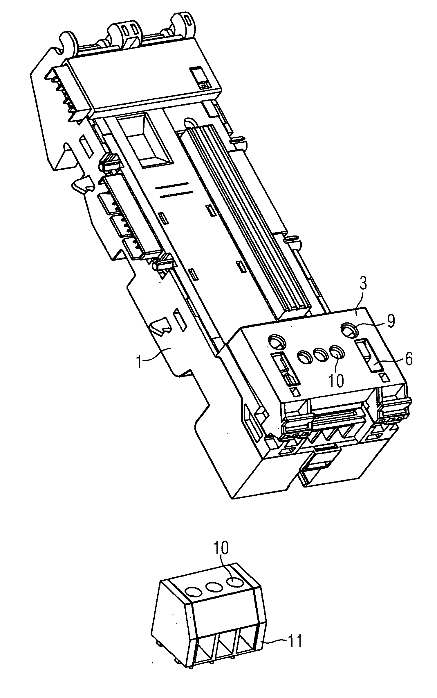
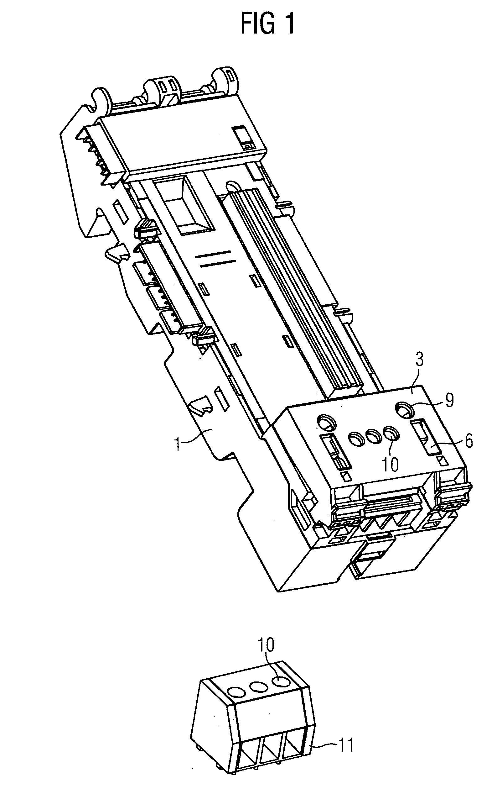
[0036]FIG. 1 shows a terminal module 1 having a sliding catch 3. The catch 3 has a first opening 6 for receiving a hooked catch 7 of a subassembly 2 or a power supply module (PS module). In addition, the catch 3 has second openings 9 for operating fixing means 8, for example a screw. There can be one or more of such openings 9, so that a different number of fixing means 8 can be used. The fixing means 8 are used for fixing the terminal module 1 on a mounting rail. In addition, the catch 3 has third openings 10 for operating a terminal 11. Breaking contacts 4 are rigidly connected to the catch 3.

[0037] Movement of the catch 3 simultaneously causes movement of the breaking contacts 4. The electrical contacts 4 are forced to open when pulling out or plugging in, or when hinging on or hinging off, a subassembly 2 or a power supply module 2. Retention of the power supply PS in the operating state is simultaneously guaranteed.

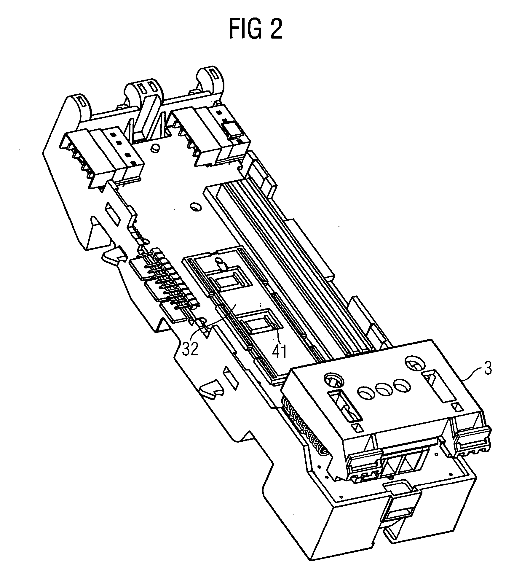
[0038] FIG 2 shows a perspective view from above of a termina...


PUM


Abstract

Retention of replaceable subassemblies, with automatic forced disconnection. The invention relates to a terminal module 1 for locking a subassembly or a PS module 2 on the terminal module in a way that satisfies safety requirements. The subassembly 2 is hinged onto the terminal module 1. The terminal module 1 has a sliding catch 3 for fixing the subassembly 2 on the terminal module 1. Disconnection of electrical contacts is guaranteed during the hinging-on.

Description

CROSS REFERENCE TO RELATED APPLICATIONS [0001] This application claims priority to the European application No. 04008070.7, filed Apr. 2, 2004 and which is incorporated by reference herein in its entirety. FIELD OF INVENTION [0002] The invention relates to a terminal module for accommodating at least one subassembly, in particular a power supply module. BACKGROUND OF INVENTION [0003] Electrical apparatus, devices and equipment are often designed to be modular, redundant and interchangeable so that they are more adaptable to the requirements of the user. If the modular device is an electrical control system then a practical modularity is usually achieved by splitting into passive (interference-resistant) terminal modules and active (and hence interference-prone) subassemblies or electronic modules. The control system function required by the customer is ultimately achieved by linking together a number of terminal modules and electronic modules. [0004] Similarly, the power supply comp...

Claims


Application Information

Patent Timeline
IPC IPC(8): H01H9/20H01R4/66H05K7/12H05K7/14
CPCH05K7/1478
Inventor BRADA, RALFBRAUNLICH, MICHAEL
Owner SIEMENS AG
Why Eureka
Try Eureka