
Imaging device analysis systems and imaging device analysis methods

a technology of imaging device and analysis system, which is applied in the field of imaging device analysis system and imaging device analysis method, can solve the problems of insufficient accuracy of calibration implemented using reflective charts for use with cameras, inconvenient calibration procedure of monochromator, and high cost of devices

Active Publication Date: 2005-10-06
HEWLETT PACKARD DEV CO LP
View PDF48 Cites 205 Cited by
  • Summary
  • Abstract
  • Description
  • Claims
  • Application Information

AI Technical Summary

Benefits of technology

[0009] According to one embodiment, an imaging device analysis system comprises a light source configured to output light for use in analyzing at least one imaging component of an imaging device, wherein the imaging device is configured to generate images responsive to received light, and processing circuitry coupled with the light source and configured to control th

Problems solved by technology

However, calibrations implemented using reflective charts may not be accurate enough for utilization with cameras.
However, the calibration procedure with monochromators may take a relatively long period of time to complete, the devices are expensive, and an accurate and controlled light source is typically used.
Other conventional arrangements for analyzing imaging devices have associated drawbacks.
For example, one device for shutter testing of an imaging device (e.g., a Camlogix SH-T2) utilizes incandescent lamps and a time calibrated sensor placed in a film plane of a film camera which is less practical for testing of digital cameras.
Further, usage of incandescent lamps presents issues with respect to controlling the duration of illumination as well as color and luminance of emitted light.
Scanners have been calibrated using white cards which does not permit color calibration in color implementations.
These systems have drawbacks of careful set-up and being designed for analyzing television cameras.

Method used


Image

  • Imaging device analysis systems and imaging device analysis methods
  • Imaging device analysis systems and imaging device analysis methods
  • Imaging device analysis systems and imaging device analysis methods

Examples


Embodiment Construction

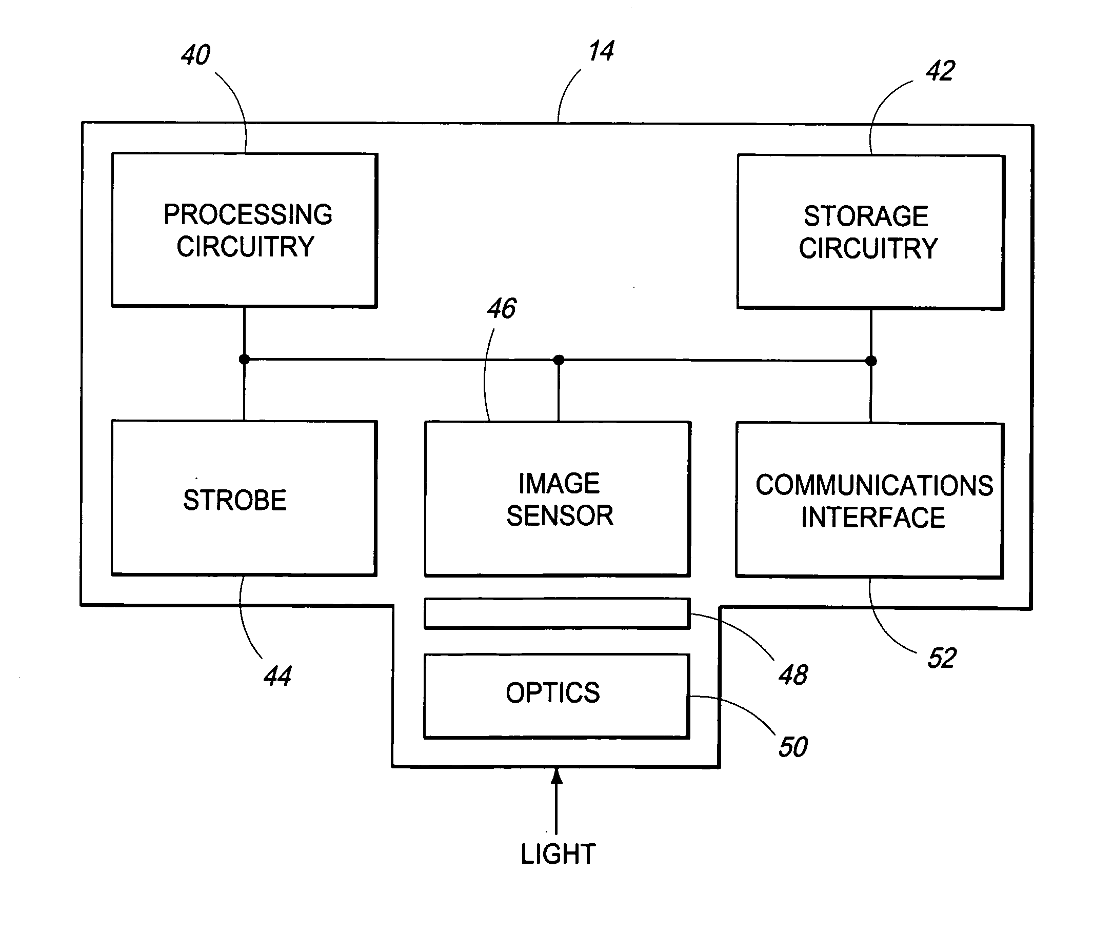
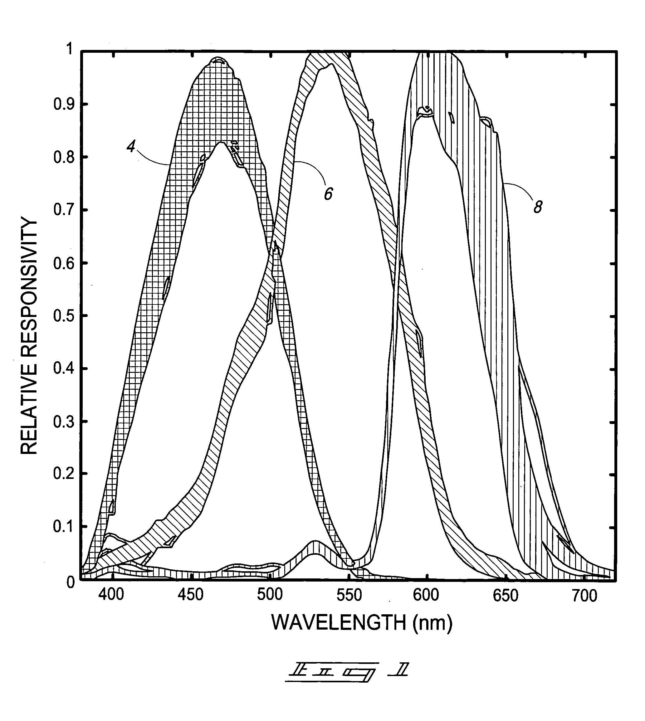
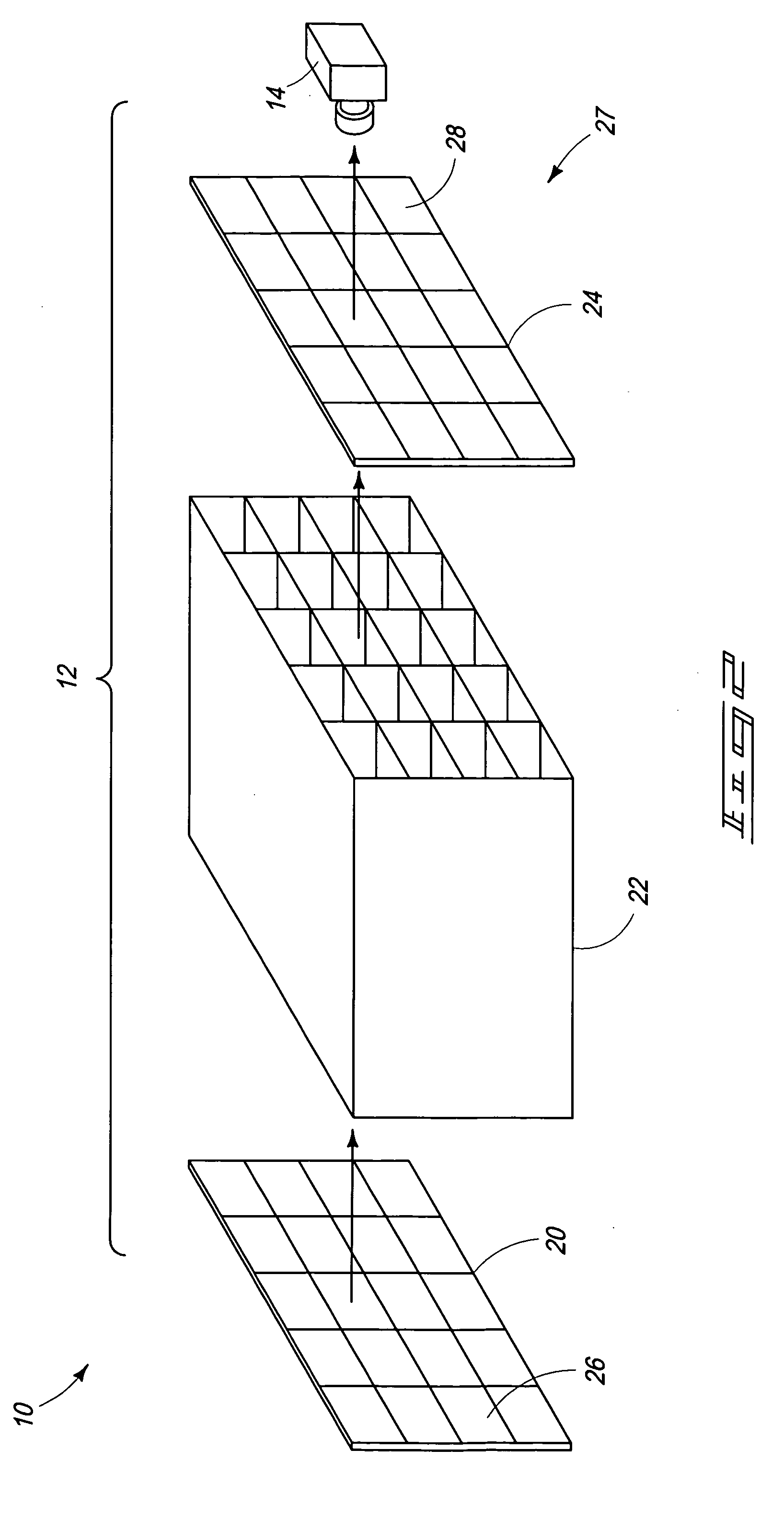
[0045] At least some aspects of the disclosure provide apparatus and methods which enable fast and accurate calibration of an imaging device. In one embodiment, optical characteristics such as a responsivity function and / or a transduction function of an imaging device may be measured to determine how the associated imaging device responds to input light signals. The determined optical characteristics may be utilized to calibrate the respective imaging device. According to exemplary implementations, emissive light sources as opposed to reflective arrangements are used to determine the optical characteristics and which enable real time fast and relatively inexpensive calibration of an imaging device (e.g., on an assembly line).

[0046] Referring to FIG. 2, an imaging system 10 according to one embodiment is shown. The depicted imaging system 10 includes an exemplary imaging device calibration instrument 12 and an imaging device 14. Instrument 12 may be referred to as an emissive calibr...


PUM


Abstract

Imaging device analysis systems and imaging device analysis methods are described. According to one embodiment, an imaging device analysis system includes a light source configured to output light for use in analyzing at least one imaging component of an imaging device, wherein the imaging device is configured to generate images responsive to received light, and processing circuitry coupled with the light source and configured to control the light source to optically communicate the light to the imaging device, wherein the processing circuitry is further configured to access image data generated by the imaging device responsive to the reception, by the imaging device, of the light from the light source and to process the image data to analyze an operational status of the at least one imaging component.

Description

RELATED PATENT DATA [0001] This application resulted from a continuation in part of and claims priority to U.S. patent application Ser. No. 10 / 818,622, filed on Apr. 5, 2004, entitled “Imaging Device Calibration Methods, Imaging Device Calibration Instruments, Imaging Devices, And Articles Of Manufacture”, listing Jeffrey M. DiCarlo as inventor, and the disclosure of which is incorporated by reference herein.FIELD OF THE DISCLOSURE [0002] Aspects of the disclosure relate to imaging device analysis systems and imaging device analysis methods. BACKGROUND OF THE DISCLOSURE [0003] Imaging systems of various designs have been used extensively for generating images. Exemplary imaging systems include copiers, scanners, cameras, and more recently digital cameras, and other devices capable of generating images. Color imaging systems have also experienced significant improvements and are increasing in popularity. Color imaging systems may be calibrated to increase accuracy of various image pr...

Claims


Application Information

Patent Timeline
IPC IPC(8): H04N1/401H04N1/48H04N1/60H04N17/00
CPCH04N1/401H04N17/002H04N1/484G01J3/524
Inventor KOHLER, TIMOTHY L.STOECKER, STEVEN D.DICARLO, JEFFREY M.GEHMAN, LESDISPOTO, GARY J.MONTGOMERY, ERICMILLER, CASEY L.
Owner HEWLETT PACKARD DEV CO LP
Learn More