
Dual polarizing light filter for 2-D and 3-D display

Inactive Publication Date: 2005-10-06
SUN LI +1
View PDF2 Cites 24 Cited by
  • Summary
  • Abstract
  • Description
  • Claims
  • Application Information

AI Technical Summary

Benefits of technology

[0024] The polarizing direction on each desired unit of the DP filter may be changed and controlled dynamically, providing the display industry, the media industry, and the computer hardware and software industry great flexibility on various areas of 3-D imaging, such as image recording, image data storing, data signal converting, signal broadcasting, signal mixing and rendering.
[0026] The invention takes advantage of modern LCD manufacturing equipment and technologies, thus the cost of the new technology evaluation is minimized. The present invention also includes the manufacture method of the DP filter. There is no conflict between 2-D image signals and 3-D image signals in using the invention. A display device with DP filter displays 2-D images naturally if 2-D image signal is rendered. An image-recording device with DP filter may record a 2-D image as well without notice. The polarizing light has no affect to the naked eyes or the light sensors in a camera for 2-D image application.

Problems solved by technology

This type of method usually has limitations such as a narrow functional view angle and small functional view region.

Method used


Image

  • Dual polarizing light filter for 2-D and 3-D display
  • Dual polarizing light filter for 2-D and 3-D display
  • Dual polarizing light filter for 2-D and 3-D display

Examples


Embodiment Construction

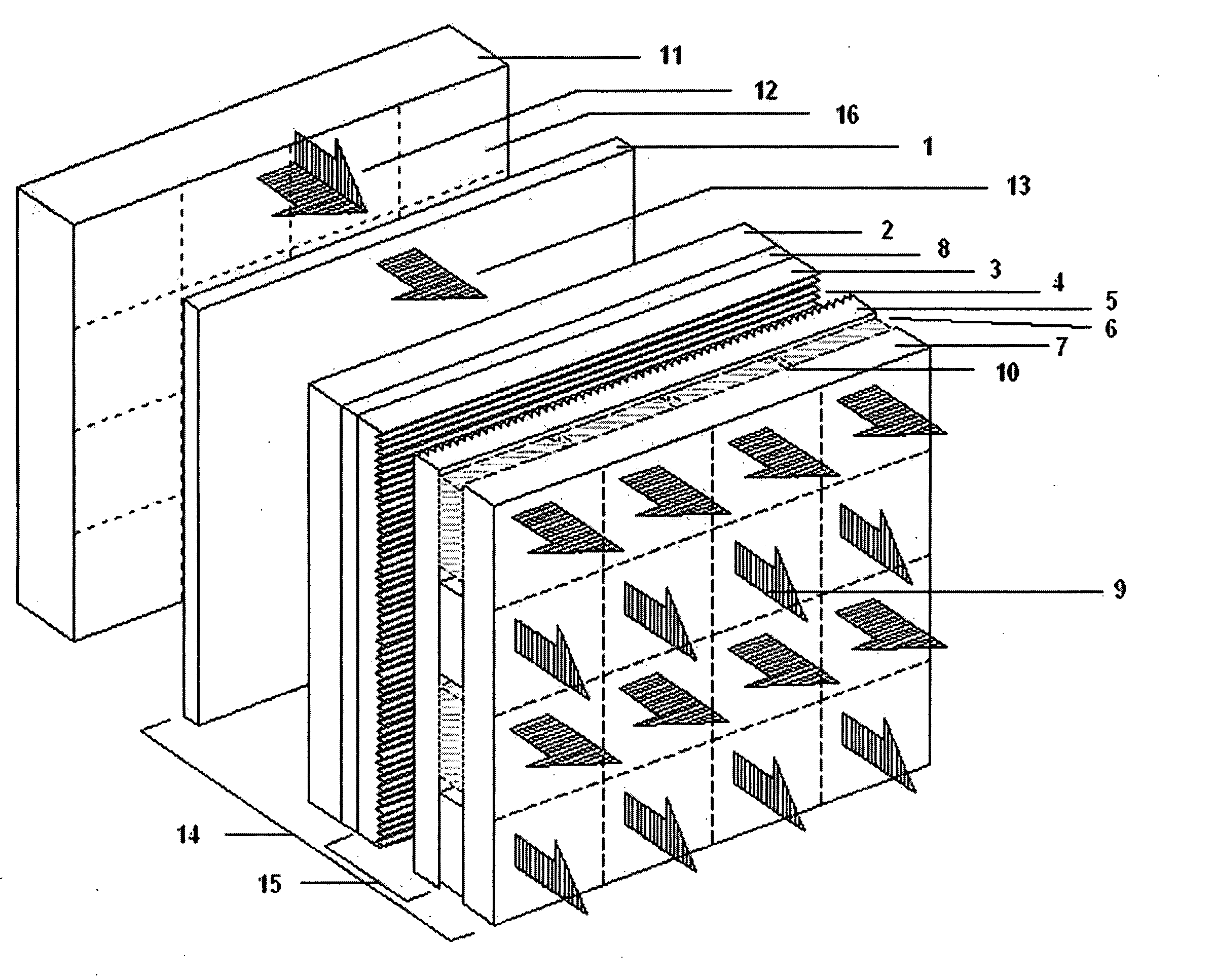
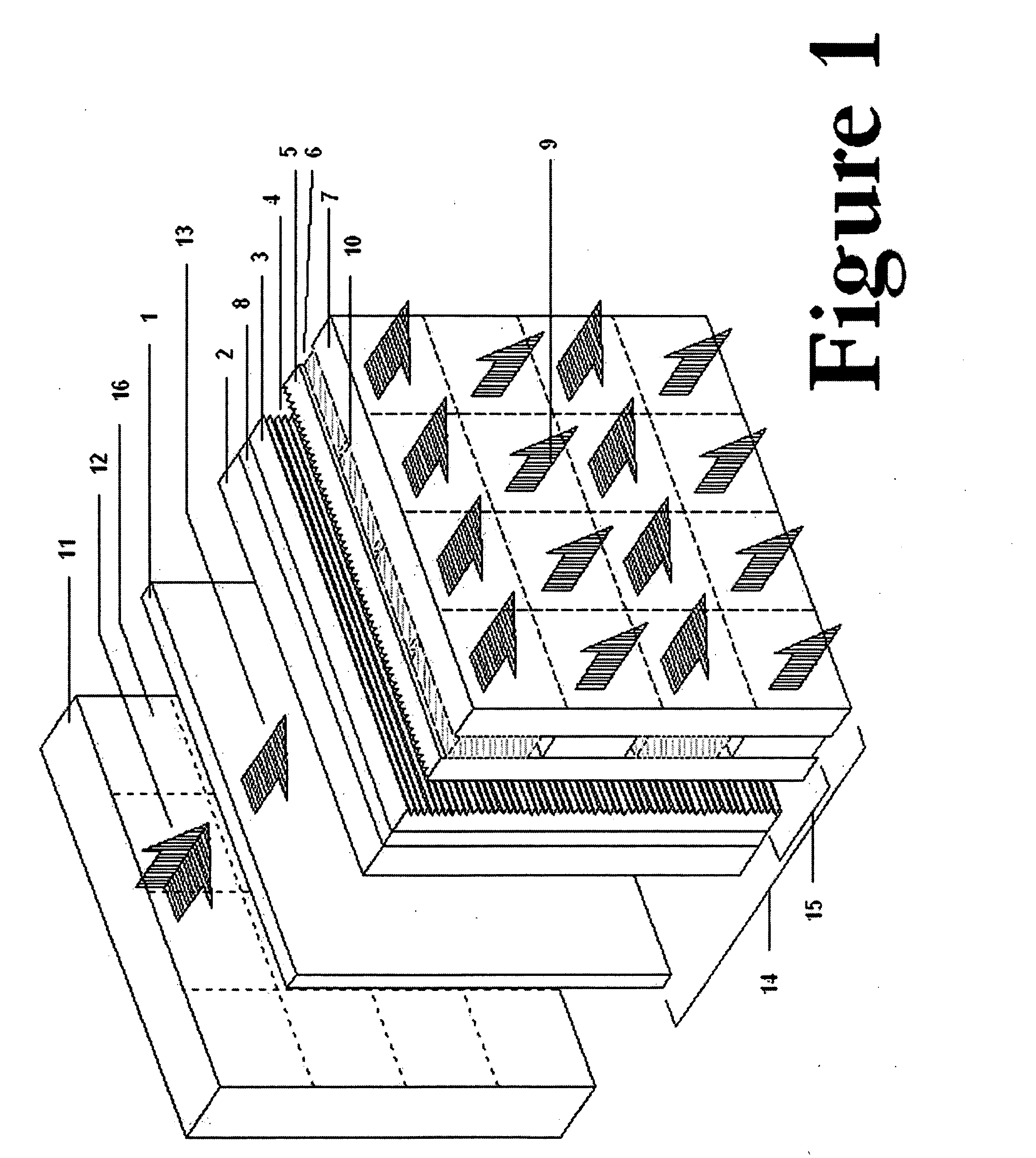
[0050]FIG. 1 is a perspective view of one embodiment of the DP Filter 14 of the present invention. First glass substrate 2 and second glass substrate 7 are facing and spaced apart from each other. A common electrode layer 8 is formed on the inner surface of first glass substrate 2. A unit polarizing control layer 6 is formed on the inner surface of second glass substrate 7. A liquid crystal sandwich structure layer 15 is formed between the unit polarizing control layer 6 and the common electrode layer 8. An optional linear polarizing film 1 is formed on the outer surface of first glass substrate 2. A display screen of any type 11 is attached to the DP Filter 14. If display screen 11 illuminates polarizing light, the linear polarizing film 1 may be omitted.

[0051] LC layer 15 may have a first alignment layer 3 and a second alignment layer 5 with liquid crystal 4 filled in between of them. To maintain a uniform space between alignment layers, a spacer, (not shown) may be used between ...


PUM


Abstract

A stereoscopic display and record component, more specifically a dual polarizing light filter, and the methods of applying the component for stereoscopic image displaying and stereoscopic image recording, are disclosed. A dual polarizing light filter may be statically or dynamically controlled to deliver or accept polarizing light of different orientations at different micro regions on the filter at different times. The invention may be used to create a new type display device and a new type of recording method for both 2-D and 3-D images. The component may be added to existing displays as well as integrated into the display fabrication process.

Description

CROSS-REFERENCE TO RELATED APPLICATIONS [0001] The present application claims priority from Provisional U.S. Patent Application No. 60 / 558,898 filed on Apr. 3, 2004, and incorporated herein by reference.FIELD OF THE INVENTION [0002] The presented invention relates to a three-dimensional (3-D) image display method and apparatus and 3-D image record method and apparatus, both using polarized light, and more particularly, relates to a combined two-dimensional (2-D) and three-dimensional display and recording method and apparatus. BACKGROUND OF THE INVENTION [0003] Humans perceive the real world through two views obtained by both eyes, using so-called stereoscopic vision. The human brain interprets the two views, generates space distance from the views and thus forms a 3-D vision. A 3-D displaying method is the method for simulating the stereoscopic observing process. [0004] There are basically two types of three-dimensional (3-D) display methods: auto-stereoscopic display and stereosco...

Claims


Application Information

Patent Timeline
IPC IPC(8): G02B30/25H04N9/47H04N13/00H04N13/04H04N15/00
CPCG02B27/26H04N13/021H04N13/0454H04N13/0438H04N13/0434G02B30/25H04N13/211H04N13/337H04N13/341H04N13/359
Inventor SUN, LILAO, WANMING
Owner SUN LI
Learn More